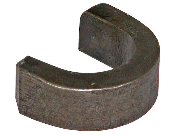
The Buyers Products Flange of Beam Weld Bracket for B23510 Outrigger welds to the flange of the beam. Two are required per outrigger.
Specifications
| Height (in.) | - |
|---|---|
| Usable Width (in.) | - |
Advanced Engineering and Application of the Flange of Beam Weld Bracket for B23510 Outriggers
In the realm of heavy-duty equipment and specialized vehicle integration, the structural integrity and stability of ancillary components are paramount. The Buyers Products Flange of Beam Weld Bracket represents a critical engineering solution specifically designed to facilitate the secure mounting of the B23510 Ductile Iron Outrigger. This detailed technical exposition will delve into the design philosophy, material science considerations, installation methodologies, and the overarching importance of this precision-engineered bracket in demanding operational environments.
Understanding the B23510 Ductile Iron Outrigger System
Before dissecting the mounting bracket itself, it is imperative to comprehend the function and characteristics of the component it supports: the B23510 Ductile Iron Outrigger. Outriggers are fundamental stability-enhancing devices widely employed on mobile equipment such as cranes, aerial work platforms, service trucks, and other specialized vehicles that require a stable, level platform for safe operation. They extend laterally from the vehicle chassis, providing a broader base of support that significantly increases the equipment's tipping resistance and load-bearing capacity. The designation "Ductile Iron" for the B23510 outrigger is highly significant. Ductile iron, also known as nodular cast iron, is a class of cast irons characterized by the spherical graphite nodules within its microstructure, as opposed to the flake-like graphite found in gray cast iron. This unique microstructure imparts superior strength, ductility, and impact resistance compared to traditional cast irons, making it an excellent material choice for components subjected to high static and dynamic loads, such as outriggers. The inherent properties of ductile iron – high yield strength, good machinability, and excellent castability – make it suitable for manufacturing complex outrigger geometries that must withstand considerable compressive, tensile, and torsional stresses during deployment and operation. The B23510 outrigger, therefore, is a robust and essential safety component, and its secure attachment to the vehicle's structural frame is non-negotiable for operational safety and equipment longevity.
The Engineering of the Mounting Bracket: Design and Materiality
The Buyers Products Flange of Beam Weld Bracket is not merely a piece of metal; it is a precisely engineered interface between a high-stress component (the outrigger) and the primary structural frame (the beam flange) of a heavy-duty vehicle. Its design is predicated on rigorous principles of mechanical engineering, material science, and structural analysis to ensure optimum performance and safety. While specific dimensional data like Height (in.) and Usable Width (in.) are left undefined in the provided specifications, these critical parameters would typically be meticulously calculated based on the B23510 outrigger's mounting pattern, the structural properties of the target beam flange, and the anticipated load conditions.
The bracket's primary function is to transfer the substantial forces exerted by the outrigger – including compressive forces when the outrigger bears weight, tensile forces during rebound or uneven terrain operation, and shear forces from lateral movements – directly into the vehicle's main chassis beam. This force transfer must occur efficiently and without inducing detrimental stress concentrations in either the bracket or the beam. The material chosen for such a bracket is typically high-strength steel, often conforming to ASTM A36, A572 Grade 50, or similar structural steel specifications. These materials offer an optimal balance of yield strength, tensile strength, weldability, and fatigue resistance crucial for components in dynamic, high-load environments. The bracket's geometry is designed to distribute loads evenly across its contact area with both the outrigger and the beam flange, minimizing localized stress points that could lead to premature failure. Features such as reinforced gussets, specific hole patterns for outrigger attachment, and a precisely contoured base for optimal welding contact are integral to its functionality. The manufacturing process involves precision cutting, forming, and machining to achieve tight tolerances, ensuring a proper fit and consistent weld joint geometry. Surface preparation, often including sandblasting or chemical treatment, is critical prior to welding to ensure optimal adhesion and weld quality.
The Critical Process of Welding to the Flange of the Beam
The method of attachment, "welds to the flange of the beam," is a defining characteristic of this bracket and underscores its permanent, high-strength integration. Welding is a metallurgical joining process that offers superior structural integrity compared to mechanical fasteners when executed correctly. However, it also demands significant technical expertise and adherence to stringent standards. The "flange of the beam" typically refers to the horizontal top or bottom plate of an I-beam or H-beam, which are common structural elements in vehicle chassis. This area is chosen for its direct load path to the beam's web and its relatively flat, accessible surface for welding.
Key considerations for the welding process include:
- Material Compatibility and Weldability: The bracket's material (e.g., structural steel) must be metallurgically compatible with the beam's material. Most vehicle chassis beams are also constructed from various grades of structural steel, simplifying compatibility. However, understanding the carbon equivalent and alloy content of both materials is crucial to select appropriate welding consumables (electrodes or wires) and pre/post-weld heat treatment procedures.
- Welding Process Selection: Common welding processes suitable for this application include Shielded Metal Arc Welding (SMAW), Gas Metal Arc Welding (GMAW/MIG), or Flux-Cored Arc Welding (FCAW). The choice depends on factors such as environmental conditions, required deposition rate, material thickness, and welder skill. Each process has specific advantages in terms of penetration, bead quality, and efficiency.
- Joint Design and Preparation: The bracket would typically be designed for fillet welds or partial penetration groove welds. Proper joint preparation, including cleaning (removal of paint, rust, oil, scale), beveling if necessary, and achieving a tight fit-up, is paramount. Gaps or misalignment can lead to inadequate fusion and weakened joints.
- Welding Procedures and Parameters: Adherence to a qualified Welding Procedure Specification (WPS), typically conforming to American Welding Society (AWS) D1.1 Structural Welding Code – Steel, is essential. This document specifies parameters such as amperage, voltage, travel speed, preheat temperature, interpass temperature, and number of passes. Proper preheating of thicker sections or certain steel grades is often necessary to prevent hydrogen-induced cracking and ensure adequate fusion.
- Welder Qualification: The welding must be performed by certified welders who have demonstrated proficiency in the relevant welding processes, positions, and materials, as per AWS D1.1 or equivalent international standards.
- Quality Assurance and Inspection: Post-weld inspection is critical. Visual inspection for defects such as cracks, porosity, undercut, and insufficient fusion is the first step. Non-destructive testing (NDT) methods like magnetic particle testing (MPT), liquid penetrant testing (LPT), ultrasonic testing (UT), or radiographic testing (RT) may be employed for critical applications to detect subsurface flaws and ensure the integrity of the weld joint.
- Stress Relief: For highly constrained joints or certain high-strength steels, post-weld heat treatment (PWHT) or stress relief annealing might be necessary to mitigate residual stresses induced by the welding process, thereby reducing the risk of brittle fracture or distortion.
The successful execution of this welding process ensures that the bracket becomes an integral, monolithic extension of the vehicle's structural beam, capable of enduring the repetitive and demanding loads associated with outrigger operation.
Structural Integrity and Load Bearing Capacity
The paramount concern for any component within a heavy equipment system is its ability to safely bear and distribute loads. The Flange of Beam Weld Bracket is engineered to transfer the compressive, tensile, and shear forces from the B23510 outrigger directly into the robust structural beam of the vehicle chassis. When an outrigger is deployed and supporting a significant portion of the vehicle's weight and payload, the bracket experiences substantial compressive forces. Conversely, if the outrigger is subjected to uplift forces or dynamic loading, the bracket must withstand tensile stresses. Lateral forces, arising from uneven terrain or dynamic operational shifts, introduce shear stresses. The design accounts for these complex multi-axial loading conditions, ensuring that stress concentrations are minimized and distributed effectively across the weld joint and the bracket's geometry.
The structural integrity is not solely dependent on the bracket itself but is a system property. It relies on the robust design of the B23510 outrigger, the strength of the vehicle's main beam, and crucially, the quality of the welded connection. Finite Element Analysis (FEA) would typically be employed during the design phase to simulate various load scenarios, predict stress distributions, identify potential failure points, and optimize the bracket's geometry and material thickness to meet specified safety factors. The bracket must be designed with an adequate safety margin to account for dynamic loads, fatigue cycles over the equipment's lifespan, potential environmental degradation (corrosion), and manufacturing variations. Furthermore, the design must consider the potential for localized yielding in extreme overload situations, ensuring that failure, if it occurs, is ductile and predictable rather than sudden and catastrophic.
The Significance of "Two are Required Per Outrigger"
The specification that "Two are required per outrigger" is a critical design directive with profound implications for load distribution, stability, and redundancy. This requirement indicates that a single outrigger unit is attached at two distinct points along its length or at two separate interface points with the vehicle chassis. This dual-point attachment offers several key advantages:
- Enhanced Stability and Torsional Resistance: By securing the outrigger at two points, the system gains significantly improved resistance to torsional forces. When an outrigger extends and retracts, or when it experiences uneven ground contact, it can generate twisting moments. A dual-bracket system effectively counteracts these moments, preventing unwanted rotation or bending of the outrigger relative to the chassis.
- Improved Load Distribution: Distributing the outrigger's load across two separate brackets and weld joints ensures that the stresses are spread over a larger area of the vehicle's structural beam. This reduces the localized stress on any single point, mitigating the risk of material fatigue or deformation in both the bracket and the chassis. It also provides a more balanced transfer of forces from the outrigger into the vehicle's frame.
- Redundancy and Safety Factor: In demanding applications, even minor component failure can have catastrophic consequences. Requiring two brackets introduces a degree of redundancy. Should one bracket or its associated weld joint experience an unforeseen issue, the second bracket can still provide a measure of support, preventing immediate and total failure. This redundancy significantly enhances the overall safety factor of the outrigger system.
- Prevention of Articulation and Movement: A single mounting point, especially on a heavy-duty outrigger, could potentially act as a pivot, allowing undesired articulation or movement of the outrigger relative to the chassis under dynamic loads. Two well-spaced mounting points rigidly fix the outrigger's base, ensuring that it remains precisely positioned and aligned throughout its operational cycle.
- Optimized Design for Outrigger Mechanics: The B23510 Ductile Iron Outrigger likely has a design that inherently requires two support points to function optimally and safely. This could be due to its length, weight, the forces it manages, or its operational mechanism (e.g., slide-out, pivot-down). The bracket system is tailored to complement the outrigger's mechanical design.
This dual-bracket requirement underscores a robust engineering approach, prioritizing stability, load management, and safety in heavy equipment operation.
Quality Assurance and Compliance Standards
For a product like the Buyers Products Flange of Beam Weld Bracket, adherence to rigorous quality assurance protocols and industry standards is non-negotiable. Manufacturing processes must conform to quality management systems such as ISO 9001, ensuring consistency in material sourcing, fabrication, and finishing. Material certifications (Mill Test Reports) confirming the chemical composition and mechanical properties of the steel used are essential. Dimensional inspections throughout the manufacturing cycle guarantee that the brackets meet design specifications precisely. For the end-user, it is imperative that the installation process, particularly the welding, also adheres to recognized standards. This typically involves compliance with AWS D1.1 for structural welding, which covers qualification of welders, welding procedures, and inspection criteria. Furthermore, the overall equipment system, once the outriggers and brackets are integrated, must comply with relevant safety standards and regulations for heavy machinery, such as those promulgated by OSHA (Occupational Safety and Health Administration) in the U.S., or equivalent international bodies. These regulations often specify requirements for outrigger stability, load charts, and operational safety protocols. The "Buyers Products" brand name implicitly suggests a commitment to these industry standards and a focus on reliability and performance in demanding applications.
Installation, Maintenance, and Longevity
While the bracket itself is a passive component once welded, its longevity and the overall integrity of the outrigger system depend significantly on correct installation and diligent maintenance. Professional installation by certified welders, adhering to the aforementioned standards, is paramount. This includes thorough surface preparation of the beam flange, accurate positioning of the bracket, executing qualified weld procedures, and performing post-weld inspection. Any deviation from these practices can compromise the structural integrity of the entire system.
Post-installation, regular inspection of the welded brackets is crucial for proactive maintenance. Inspections should include:
- Visual Inspection: Checking for any signs of cracking in the weld joint or the surrounding parent material of the bracket or beam, corrosion, deformation, or loose components attaching the outrigger to the bracket.
- Non-Destructive Testing (NDT): Periodically, NDT methods (e.g., MPT) may be employed in critical areas, especially after sustained heavy use or if visual inspections reveal anomalies.
- Corrosion Control: Ensuring that the brackets are protected from environmental corrosion. This may involve proper painting, coating, or galvanization. Any signs of paint degradation or rust should be addressed promptly to prevent material degradation.
- Fastener Integrity: If the outrigger attaches to the bracket using bolts, these fasteners must be regularly checked for correct torque specifications and signs of wear or loosening.
The lifespan of the weld bracket system is directly correlated with the quality of its initial installation, the severity of the operational environment, and the consistency of its maintenance regimen. Designed and installed correctly, these brackets are intended to provide reliable service for the operational lifetime of the heavy equipment they support, ensuring consistent stability and safety.
Conclusion
The Buyers Products Flange of Beam Weld Bracket for the B23510 Ductile Iron Outrigger is a testament to precision engineering in the heavy equipment sector. Far from being a simple connector, it is a meticulously designed structural element crucial for the safe and effective operation of vehicles equipped with stability-enhancing outriggers. Its design, material selection, and required installation methodology—welding to the flange of the beam with two brackets per outrigger—are all carefully orchestrated to manage complex load transfers, enhance stability, and provide critical redundancy. Understanding the technical intricacies of this component underscores its indispensable role in ensuring both the performance and the paramount safety of heavy-duty machinery across diverse and demanding applications. It exemplifies the principle that in heavy engineering, the strength of the whole is critically dependent on the integrity of its foundational components.