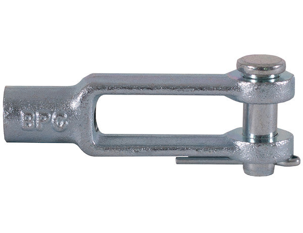
Buyers Products Clevis Rod End with Pin and Cotter Pin is used for pivot point linkages on air cylinders, shafts, rods, and other assemblies. The kit comes complete with a clevis pin and cotter pin for fast assembly. It is zinc-plated for corrosion resistance and comes in multiple sizes for a variety of applications.
Specifications
| Base to Hole Center (in.) | 2.500 |
|---|---|
| Bottom of Clevis Pin Head to Bottom of Pin (Maximum Usable Length) | 1.094 |
| Center Hole to Neck (in.) | 1.625 |
| Chamfer Angle | 15 |
| Chamfer Length | .078 |
| Clevis Pin Diameter | .375 |
| Clevis Pin Head Bevel Length | .125 |
| Clevis Pin Head Diameter | .500 |
| Clevis Pin Hole Dia. (in.) | 0.688 |
| Clevis Pin Hole Drill Number | 38 |
| Clevis Pin Incl. (y/n) | Yes |
| Color | Zinc |
| Finish | Zinc Plated |
| Height of Yoke Arm (in.) | 0.625 |
| Hole Dia. (in.) | 0.375 |
| Inner Arm to Arm (in.) | 0.438 |
| Material | Forged Steel |
| Neck Dia. (in.) | 0.625 |
| Neck Length (in.) | 0.875 |
| NOTUSED | .938 |
| Overall Pin Length | 1.219 |
| Thread Size (in.) | 1/4-28 |
| Type | Standard |
| Width (in.) | 0.875 |
Comprehensive Technical Overview: B27084A14Z 3/8 Inch Clevis with Pin and Cotter Pin Kit - Zinc Plated
The B27084A14Z Clevis Rod End, a precisely engineered component from Buyers Products, represents a robust solution for establishing pivotal linkages in a wide array of mechanical and hydraulic systems. This kit, meticulously designed for demanding applications, provides a complete assembly including the clevis body, a corresponding clevis pin, and a cotter pin, ensuring immediate and secure deployment. Its construction from forged steel, complemented by a zinc-plated finish, underscores its suitability for environments where durability, reliable performance, and resistance to environmental degradation are paramount.
A clevis rod end functions as a critical mechanical interface, translating linear motion from components such as hydraulic or pneumatic cylinders, actuating rods, or linkage arms into rotational or pivotal movement. The design of the clevis, characterized by its U-shaped yoke, facilitates a secure and flexible connection point, allowing for angular displacement between connected parts while maintaining structural integrity. The inclusion of a pin and cotter pin in this comprehensive kit streamlines assembly processes and guarantees a robust locking mechanism, preventing accidental disconnection under operational stresses.
Detailed Component Analysis
The Clevis Body
The core of this assembly, the clevis body, is fabricated from forged steel. Forging is a manufacturing process that enhances the material's grain structure, aligning it with the direction of maximum stress during operation. This results in superior strength-to-weight ratios, increased fatigue resistance, and enhanced toughness compared to components manufactured through casting or machining alone. The integral neck of the clevis is designed for direct attachment to threaded shafts or rods, providing a rigid connection point to the primary moving mechanism. The arms of the clevis form the yoke, precisely spaced and bored to accommodate the clevis pin with minimal clearance, facilitating smooth pivotal action while effectively distributing loads across the pin.
The Clevis Pin
The 3/8-inch diameter clevis pin is engineered to serve as the critical pivot axis within the clevis assembly. Its robust construction ensures that it can withstand significant shear forces and bending moments inherent in pivot point linkages. The pin features a distinct head on one end, which acts as a positive stop, preventing it from passing entirely through the clevis yoke and the connected component. The opposing end of the pin is bored with a transverse hole, specifically designed for the insertion of a cotter pin. This dual retention strategy – the head and the cotter pin – ensures that the clevis pin remains securely in place throughout the operational cycle, even under dynamic loading conditions or vibration.
The Cotter Pin
The cotter pin, a simple yet highly effective fastening device, is supplied to secure the clevis pin within the assembly. Once the clevis pin is inserted through the clevis arms and the mating component, the cotter pin is passed through the pre-drilled hole in the clevis pin. Its ends are then spread, creating a positive lock that mechanically prevents the clevis pin from withdrawing. This inexpensive yet essential component provides a fail-safe mechanism, crucial for applications where component integrity and operational safety are paramount. The inclusion of all three components in a single kit simplifies procurement and ensures compatibility.
Material and Finish Superiority
Forged Steel Construction
The choice of forged steel for the B27084A14Z clevis is a testament to its intended use in high-stress, high-reliability applications. Forging involves shaping metal while it is solid, typically through hammering, pressing, or rolling. This process refines the grain structure, eliminating porosity and internal voids often found in cast parts. The resulting component possesses anisotropic properties, meaning its strength is optimized along specific axes, typically aligning with the direction of the forces it is designed to endure. This makes forged steel components exceptionally strong, durable, and resistant to impact, fatigue, and wear, ensuring a longer service life under strenuous operating conditions.
Zinc Plated Finish
The zinc-plated finish applied to this clevis kit provides a critical layer of protection against environmental degradation, specifically corrosion. Zinc plating involves electrodepositing a thin layer of zinc onto the surface of the steel. Zinc acts as a sacrificial coating; when exposed to corrosive elements like moisture, salt, and various industrial chemicals, the zinc corrodes preferentially to the underlying steel, thereby protecting the base material. This electroplated coating significantly extends the operational lifespan of the clevis, reducing maintenance requirements and preserving the aesthetic and functional integrity of the component. The zinc finish also provides a smooth, uniform surface, which can contribute to reduced friction in dynamic applications and enhance the overall appearance of the installed part. This protective layer is particularly vital for applications exposed to outdoor elements, high humidity, or chemical atmospheres, where untreated steel would quickly succumb to rust and degrade performance.
In-Depth Analysis of Specifications
Understanding the precise dimensions and characteristics of the B27084A14Z clevis is crucial for proper integration into mechanical systems. Each specification provided plays a vital role in dictating the component's fit, function, and performance:
- Base to Hole Center (2.500 in.): This critical dimension defines the linear distance from the mounting base or the reference plane of the clevis to the central axis of the clevis pin hole. It is fundamental for establishing the effective linkage length and influences the geometric alignment and kinematic relationships within a mechanical assembly. Engineers rely on this measurement for accurate design layouts, ensuring correct lever arm ratios and predictable operational characteristics in complex systems.
- Bottom of Clevis Pin Head to Bottom of Pin (Maximum Usable Length) (1.094 in.): This specification indicates the maximum effective length of the clevis pin that can engage through the clevis arms and any intervening component (e.g., a rod eye or mounting bracket) before the cotter pin hole or other retaining feature is encountered. It is paramount for selecting appropriate mating components and ensuring full engagement of the pin, which is essential for secure retention and load transfer within the assembly.
- Center Hole to Neck (1.625 in.): This measurement quantifies the distance from the centerline of the clevis pin hole to the point where the clevis body transitions into its cylindrical or threaded neck section. This dimension significantly contributes to the overall structural length of the clevis and influences how the clevis body integrates with threaded rods, shafts, or other attachment mechanisms, impacting the overall form factor of the linkage.
- Chamfer Angle (15 degrees) and Chamfer Length (.078 in.): These precise details relate to the angled relief cuts applied to specific edges of the clevis, typically at the entrance to holes or along external contours. Chamfers serve multiple functional purposes: they reduce stress concentrations at sharp corners, facilitate easier component insertion by guiding pins or mating parts into position, and eliminate sharp edges that could cause injury or damage to cables or adjacent components. The specified 15-degree angle and 0.078-inch length reflect a deliberate engineering choice for enhanced durability, assembly ease, and operator safety.
- Clevis Pin Diameter (.375 in.): This dimension, precisely 3/8 inch, is the nominal diameter of the clevis pin itself. It is a fundamental parameter for calculating the load-bearing capacity of the pin in shear and bending, as well as ensuring proper fit within the clevis arms and any corresponding mating eyelet or hole. A precisely toleranced diameter minimizes radial play, which is crucial for efficient load transfer and accurate control in pivotal linkages.
- Clevis Pin Head Bevel Length (.125 in.): This specification describes the length of the tapered edge present on the head of the clevis pin. The primary function of this bevel is to facilitate smoother insertion of the pin into the clevis arms and reduce the potential for snagging or interference with adjacent components during assembly or operation. It contributes to both functional ease of use and the finished quality of the component.
- Clevis Pin Head Diameter (.500 in.): This refers to the diameter of the enlarged head of the clevis pin. The head serves as a positive mechanical stop, effectively preventing the pin from passing completely through the clevis and the secured component. This dimension is vital for ensuring secure retention of the pin and proper distribution of loads at the pin's head, which directly impacts the safety and structural integrity of the entire linkage assembly.
- Clevis Pin Hole Dia. (0.688 in.): This specifies the diameter of the transverse hole drilled through the shaft of the clevis pin, intended for the insertion of a cotter pin or other retaining device. The precise 0.688-inch diameter is critical for ensuring a snug and secure fit for the cotter pin, which in turn prevents accidental dislodgement of the main clevis pin, even under dynamic loads or vibrational forces.
- Clevis Pin Hole Drill Number (38): This indicates the standard drill bit size (Number 38, corresponding to a specific diameter) used in the manufacturing process to create the cotter pin hole in the clevis pin. Adhering to a standardized drill number ensures consistency in manufacturing, guarantees compatibility with widely available standard cotter pins, and simplifies replacement and maintenance procedures in the field, reducing potential downtime.
- Clevis Pin Incl. (y/n) (Yes): This explicit confirmation signifies that the clevis pin is provided as an integral part of this product kit, offering a complete and ready-to-assemble solution. This detail is highly beneficial for procurement and simplifies the bill of materials for end-users, ensuring that all necessary primary components for establishing linkage functionality are supplied upfront.
- Color (Zinc) and Finish (Zinc Plated): These specifications collectively confirm the visual appearance and the protective surface treatment of the component. The zinc plating process results in a distinctive silvery-gray metallic finish, and more importantly, it imparts superior corrosion resistance to the forged steel base material. This protective layer is crucial for extending the operational life of the clevis assembly, particularly in environments prone to moisture, chemicals, or other corrosive agents.
- Height of Yoke Arm (0.625 in.): This dimension represents the vertical thickness of each arm within the clevis yoke. It is a critical factor for determining the structural rigidity and inherent strength of the clevis. The arm height directly impacts the clevis's capacity to withstand shear and tensile forces, ensuring that the component can effectively transfer operational loads without experiencing deformation, yielding, or ultimate failure.
- Hole Dia. (0.375 in.): This refers to the primary through-hole diameter present in the clevis arms, which is precisely designed to accommodate the 3/8-inch clevis pin. The accuracy of this 0.375-inch diameter ensures a minimal clearance fit with the pin, which is essential for minimizing slop, backlash, and maximizing the efficiency of load transfer in pivotal linkages, contributing to precise control.
- Inner Arm to Arm (0.438 in.): This critical internal measurement defines the clear maximum width available between the two arms of the clevis yoke. It dictates the maximum permissible thickness of any mating component (such as an eyelet, rod end, or mounting plate) that can be inserted and securely retained within the clevis. A precisely maintained inner width is vital for ensuring proper fitment, minimizing undesirable lateral movement, and preventing binding of the connected components.
- Material (Forged Steel): This fundamental specification highlights the base material and its manufacturing process. Forged steel is renowned for its exceptional strength, superior toughness, and enhanced resistance to fatigue compared to alternative manufacturing methods like casting or simple machining from bar stock. The forging process strategically aligns the internal grain structure of the steel, thereby significantly improving its mechanical properties and making it an ideal choice for high-stress, dynamic, and safety-critical applications.
- Neck Dia. (0.625 in.): This dimension specifies the diameter of the cylindrical or threaded shank section of the clevis body. It is a crucial parameter for properly mating the clevis to corresponding threaded rods, shafts, or other components where a rigid and secure connection, separate from the pivot point, is required. The neck diameter must be compatible with the receiving threads or bore sizes of the mating components to ensure a strong and stable assembly.
- Neck Length (0.875 in.): This measurement denotes the axial length of the cylindrical or threaded 'neck' portion of the clevis. This dimension is instrumental in determining the effective engagement length for threaded connections or the maximum depth to which the clevis can be inserted into a receiving bore. Adequate neck length is essential for ensuring sufficient thread engagement, providing robust structural support, and preventing premature failure of the connection under operational loads.
- NOTUSED (.938): While present in the data structure, this entry indicates a dimension that is not actively utilized or functionally relevant for the definition or primary operational parameters of this specific B27084A14Z clevis model. It may represent a legacy dimension inherited from a broader standard, a parameter relevant to a different product variation sharing a common bill of materials, or simply an unassigned placeholder. Users should disregard this dimension when considering the functional design and integration of this particular clevis.
- Overall Pin Length (1.219 in.): This dimension refers to the total length of the clevis pin from one extremity to the other, inclusive of its head. While useful for general handling and storage considerations, the "Bottom of Clevis Pin Head to Bottom of Pin (Maximum Usable Length)" provides the more critical functional length directly applicable to assembly and component engagement.
- Thread Size (1/4-28 in.): This precisely specifies the size and pitch of the internal thread, typically located at the 'neck' of the clevis. A 1/4-inch nominal diameter with 28 threads per inch signifies a fine thread series. This fine pitch provides several advantages: it allows for more precise linear adjustment, offers superior strength due to increased thread contact area, and exhibits enhanced resistance to loosening under conditions of vibration or cyclic loading, thereby ensuring a more stable and durable connection.
- Type (Standard): This classification indicates that the clevis conforms to common industry standards for its design, dimensions, and material properties. A "Standard" type clevis ensures broad compatibility across a wide range of existing applications and systems, simplifying integration for engineers, designers, and fabricators, and reducing the complexity associated with custom component sourcing.
- Width (0.875 in.): This dimension likely refers to the overall maximum external width of the assembled clevis, typically measured across the widest part of the yoke or the head of the clevis body. This measurement is crucial for spatial planning within mechanical enclosures, ensuring that the clevis assembly fits comfortably within confined operational envelopes and maintains adequate clearances with adjacent components to prevent interference.
Applications and Industry Relevance
The B27084A14Z clevis kit is extensively utilized across numerous industries due to its robust design and reliable performance. Common applications include:
- Hydraulic and Pneumatic Systems: Essential for connecting cylinder rods to linkages, levers, or implements in heavy machinery, manufacturing automation, and material handling equipment.
- Agricultural Machinery: Used in tractors, implements, and attachments for steering linkages, control arms, and implement articulation points, where strength and corrosion resistance are vital.
- Construction Equipment: Integrated into excavators, loaders, and other heavy equipment for connecting control rods, buckets, and various articulating components, enduring harsh outdoor conditions.
- Industrial Automation: Applied in robotic arms, conveyor systems, and assembly line machinery for precision pivot points, enabling controlled movement and actuation.
- Vehicle and Trailer Manufacturing: Employed in braking systems, steering mechanisms, suspension components, and trailer hitch assemblies to provide secure, flexible connections.
- Marine Applications: The zinc plating offers critical protection in saltwater or high-humidity environments, making it suitable for boat control systems, rudder linkages, and marine equipment.
Installation and Maintenance Guidelines
Proper installation and routine maintenance are crucial for maximizing the operational lifespan and ensuring the safety of the B27084A14Z clevis kit.
- Preparation: Ensure all mating surfaces are clean, free from burrs, and dimensionally compatible with the clevis and pin.
- Assembly: Insert the clevis pin through the aligned holes of the clevis arms and the mating component. Verify that the pin head is fully seated.
- Securing: Insert the cotter pin through the cross-drilled hole in the clevis pin. Bend or spread the ends of the cotter pin outward, parallel to the clevis pin, to prevent its accidental withdrawal. Ensure the cotter pin is fully seated and securely locked.
- Torque Considerations: If the clevis neck is threaded, ensure that the mating rod or shaft is torqued to the manufacturer's specified values to achieve a secure and vibration-resistant connection, preventing loosening over time.
- Inspection: Regularly inspect the clevis, pin, and cotter pin for signs of wear, corrosion, bending, cracking, or deformation. Check for excessive play in the pivot point, which could indicate pin or hole wear.
- Lubrication: Although not typically required for a standard clevis, in high-cycle or heavily loaded applications, light lubrication on the pin-to-clevis interface may reduce wear and friction. Use a compatible lubricant appropriate for the operating environment.
- Replacement: Replace any component exhibiting significant wear, damage, or corrosion immediately to prevent catastrophic failure and ensure system integrity. Always use genuine or equivalent replacement parts that match the original specifications.
Technical Advantages and Value Proposition
The B27084A14Z clevis kit stands out due to several key technical advantages:
- Integrated Solution: Supplied as a complete kit (clevis, pin, cotter pin), it eliminates the need for separate component sourcing, simplifying inventory management and accelerating assembly.
- Superior Material Integrity: Forged steel construction provides exceptional strength, fatigue resistance, and durability, ensuring a longer operational life even in rigorous applications.
- Enhanced Corrosion Resistance: The zinc-plated finish offers robust protection against rust and environmental corrosion, maintaining structural integrity and aesthetic appeal in challenging conditions.
- Precision Engineering: Adherence to precise dimensional specifications ensures optimal fit, minimal play, and efficient load transfer, contributing to accurate and reliable mechanical linkages.
- Standardized Design: As a "Standard" type clevis, it offers broad compatibility and ease of integration into existing designs and systems, simplifying engineering processes.
- Safety Assurance: The secure pin and cotter pin retention mechanism provides a reliable pivot point, crucial for maintaining operational safety and preventing unexpected disconnections.
Conclusion
The B27084A14Z 3/8 Inch Clevis with Pin and Cotter Pin Kit, zinc-plated and constructed from forged steel, offers an unparalleled combination of strength, corrosion resistance, and precision. Its meticulous engineering, comprehensive specifications, and complete kit format make it an indispensable component for a multitude of industrial, agricultural, and mobile equipment applications. By providing a reliable, durable, and easily integrable pivot point solution, this product ensures optimal performance and longevity in the most demanding mechanical systems, solidifying its position as a preferred choice for professional engineers and fabricators seeking uncompromising quality and technical excellence.