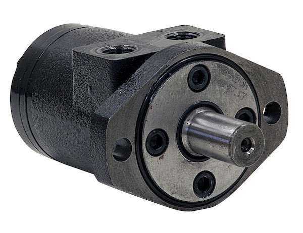
Hydraulic Motors from Buyers Products are designed to be economical, efficient, compact and powerful. They are a great solution for powering medium-duty applications like compressors, augers, winches, cranes, and spreaders. The motors have an industry-proven spool valve design combined with state-of-the-art gerotors. They excel at jobs that need a high degree of start-up torque or just the right mixture of torque and flow rate. Choose from a wide range of motors depending on your needs for flow rates, torque and starting torque. Each model is available with either a 2-bolt or 4-bolt mount. The last digit of the part number (2 or 4) will indicate the number of bolts.
Specifications
| Compares To | 101-1025-009 |
|---|---|
| Displacement | 3.1 |
| Flow (Continuous) | 12 |
| Flow (Intermittent) | 14 |
| Input Mount Type | 2 Bolt |
| Material | Cast Iron |
| Maximum Case Pressure (Without Case Drain) | 1500 |
| Maximum Speed (Continuous) | 969 |
| Maximum Speed at Continuous Flow | 969 |
| Maximum Speed at Intermittent Flow | 1130 |
| Minimum Starting Torque (Continuous Pressure) | 520 |
| Minimum Starting Torque (Intermittent Pressure) | 720 |
| Pilot Diameter | 3.25 |
| Port Size | 1/2 NPT |
| Pressure ? Bar (Continuous) | 1800 |
| Pressure ? Bar (Intermittent) | 2400 |
| Shaft Keyway | 0.25 |
| Shaft Size | 1.00 |
| Shaft Type | Straight |
| Torque Rating (Continuous) | 650 |
| Torque Rating (Intermittent) | 720 |
The Hydraulic Motor from Buyers Products, specifically the model featuring a 2-bolt mount, NPT threads, and a nominal displacement of 2.8 cubic inches (with this particular model specified at 3.1 cubic inches as detailed in the technical specifications), represents a pinnacle of hydraulic power conversion technology. Engineered for applications demanding robust performance, efficiency, and reliability, this motor is a testament to advanced design and manufacturing precision. It provides an optimal solution for driving medium-duty equipment, distinguishing itself through its high starting torque capabilities and finely balanced torque-to-flow characteristics, which are critical for precision and power in diverse operational scenarios.
Advanced Hydraulic Motor Design and Principles
Gerotor Technology: The Heart of Efficiency
At the core of this hydraulic motor's superior performance is its state-of-the-art gerotor design. Gerotor, a portmanteau of "generated rotor," refers to a positive displacement pump or motor type that utilizes an inner and outer gear set. The inner gear has one less tooth than the outer gear and is eccentrically mounted. As hydraulic fluid enters the motor, it exerts pressure on the larger surfaces of the rotating elements. The differential pressure across the gears creates a torque that causes the inner gear to rotate and orbit within the outer gear. This orbital motion is converted into rotary motion of the output shaft via a coupling spline. The benefits of this design are manifold. Gerotor motors are renowned for their high volumetric efficiency, meaning a significant portion of the input fluid flow is effectively converted into mechanical rotation, minimizing energy loss. They offer exceptionally smooth operation, especially at low speeds, which is crucial for applications requiring precise control without pulsation. Furthermore, their compact size relative to their power output, coupled with their inherent ability to generate high starting torque, positions them as an ideal choice for intermittent and continuous duty cycles where immediate power delivery is essential.
Spool Valve Design: Precision Fluid Control
Complementing the gerotor mechanism is an industry-proven spool valve design. The spool valve is integral to directing the flow of hydraulic fluid within the motor, enabling both directional control and speed regulation. By precisely controlling the paths of pressurized fluid to and from the gerotor set, the spool valve ensures efficient and responsive operation. This design minimizes internal leakage, contributing to the motor's overall efficiency and extending its operational lifespan by reducing internal wear. The robust nature of the spool valve system allows for consistent performance across varying load conditions and fluid pressures, enhancing the motor's adaptability to demanding environments and diverse application requirements.
Robust Construction: Cast Iron Durability
The choice of material for the motor housing is a critical factor in its longevity and performance. This hydraulic motor is constructed from high-grade cast iron, a material celebrated for its exceptional strength, rigidity, and inherent damping properties. Cast iron provides superior resistance to mechanical stress, thermal cycling, and external impacts, ensuring structural integrity even in the most rigorous industrial and mobile applications. Its ability to absorb vibrations contributes to quieter operation and reduces wear on internal components, thereby extending the motor's service life. Furthermore, cast iron offers excellent thermal stability, helping to dissipate heat effectively and maintain consistent internal operating temperatures, which is vital for the performance and longevity of hydraulic fluid and seals.
Mounting and Porting for Seamless Integration
2-Bolt Mount Configuration
The product features a standard 2-bolt mount, a widely adopted interface in the hydraulic industry. This configuration, typically conforming to SAE A flange standards, facilitates straightforward and secure integration into a broad spectrum of hydraulic systems. The 2-bolt pattern ensures robust mechanical coupling, capable of withstanding significant operational forces and vibrations, thereby maintaining alignment between the motor and the driven equipment. This standardization simplifies installation, reduces mounting complexity, and ensures broad compatibility with existing machinery and components, offering flexibility in system design and maintenance.
NPT Threads: Secure and Reliable Fluid Connections
Fluid connections are managed via NPT (National Pipe Taper) threads, with a specified port size of 1/2 NPT. NPT threads are a conical pipe thread type designed to create a liquid-tight seal when joined. The tapered design allows the threads to wedge together, forming a robust mechanical seal that is further enhanced by the application of thread sealant. This method of connection is highly reliable for high-pressure hydraulic applications, preventing leaks and ensuring system integrity. The 1/2 NPT size is a common and versatile choice, providing adequate flow capacity for the motor's rated performance while maintaining a manageable footprint for plumbing within diverse hydraulic circuits.
Detailed Performance Specifications and Analysis
Displacement: 3.1 Cubic Inches per Revolution
The motor's displacement is a fundamental characteristic, defining the volume of hydraulic fluid it consumes for each revolution of its output shaft. With a specific displacement of 3.1 cubic inches (cu.in.) per revolution, this motor is engineered for precise control over its speed and torque output. This value directly influences the motor's theoretical speed at a given flow rate (Speed = Flow Rate / Displacement) and its theoretical torque output at a given pressure (Torque = (Pressure × Displacement) / (2π)). The 3.1 cu.in. displacement ensures a balance between speed and torque, making it versatile for applications that require either moderate speed with high torque or higher speed with proportional torque output.
Flow Rate Performance: Continuous 12 GPM, Intermittent 14 GPM
The continuous flow rate of 12 Gallons Per Minute (GPM) indicates the maximum flow the motor can sustain indefinitely without detrimental effects to its lifespan or performance. For short durations, the motor can handle an intermittent flow rate of 14 GPM, allowing for temporary bursts of higher power or speed. These flow specifications are critical for system designers to match the motor's capabilities with the hydraulic pump's output. Operating within these parameters ensures optimal motor efficiency, prevents overheating, and maximizes the service life of the motor and associated hydraulic components. Considering the 3.1 cu.in. displacement, a continuous flow of 12 GPM (2772 cu.in./min) translates to a theoretical continuous speed of approximately 894 RPM (2772/3.1). Similarly, an intermittent flow of 14 GPM (3234 cu.in./min) yields a theoretical intermittent speed of around 1043 RPM (3234/3.1). These theoretical speeds are closely aligned with the specified maximum speeds, indicating high volumetric efficiency.
Pressure Ratings: Continuous 1800 PSI, Intermittent 2400 PSI
The motor is designed to operate safely and efficiently under a continuous pressure of 1800 Pounds per Square Inch (PSI) and can withstand intermittent pressure spikes up to 2400 PSI. These pressure ratings are indicative of the motor's structural integrity and its ability to generate substantial torque. Continuous pressure refers to the maximum pressure that can be applied constantly during operation. Intermittent pressure accounts for short, periodic increases in pressure, often encountered during demanding phases of an application (e.g., initial start-up under heavy load, brief overloads). Adhering to these pressure limits is crucial to prevent internal damage, leakage, or catastrophic failure of the motor components.
Torque Characteristics: Power Under Load
Torque is the rotational force produced by the motor, directly influencing its ability to drive a load. This motor provides a continuous torque rating of 650 lb-in (pound-inches) and an intermittent torque rating of 720 lb-in. These figures represent the actual torque output at the shaft under continuous and intermittent operating conditions, respectively, taking into account the motor's mechanical efficiency. A standout feature is its impressive starting torque: a minimum of 520 lb-in under continuous pressure and 720 lb-in under intermittent pressure. High starting torque is paramount for applications such as augers, winches, and conveyor systems that must overcome significant static friction or inertia to initiate movement. The ability to deliver strong initial rotation without excessive pressure spikes protects both the motor and the driven equipment, ensuring smooth and reliable start-up even with heavy loads.
Speed Capabilities: Maximum Continuous 969 RPM, Maximum Intermittent 1130 RPM
The motor's maximum continuous speed of 969 RPM and maximum intermittent speed of 1130 RPM demonstrate its capability to sustain significant rotational velocities for extended periods and short bursts, respectively. These speed ratings are a function of the motor's displacement and its volumetric efficiency at its maximum permissible flow rates. Maintaining operation within these speed limits is essential to prevent excessive internal friction, heat generation, and premature wear of the bearings and seals. The robust design, particularly the gerotor and spool valve mechanisms, allows for efficient operation across a wide speed range, contributing to the motor's versatility in different application profiles.
Maximum Case Pressure (Without Case Drain): 1500 PSI
The maximum case pressure rating of 1500 PSI without the need for a separate case drain line is a significant advantage. In many hydraulic motors, internal leakage from the high-pressure side to the motor casing necessitates a dedicated case drain line to prevent pressure buildup, which could blow out shaft seals. The design of this motor, however, exhibits superior sealing and internal pressure management capabilities, allowing it to tolerate a much higher internal case pressure without the aid of an external drain. This simplifies hydraulic system plumbing, reduces potential leak points, and lowers overall installation and maintenance costs. It indicates a highly robust and well-sealed motor construction, enhancing its reliability in demanding environments.
Shaft Specifications: 1.00 Straight, 0.25 Keyway, 3.25 Pilot Diameter
The output shaft is a crucial interface for transmitting power to the driven load. This motor features a 1.00-inch diameter straight shaft, which is a common and versatile design for direct coupling applications. A straight shaft provides excellent concentricity and ease of installation with standard couplings, sprockets, or pulleys. The integrated 0.25-inch keyway is machined into the shaft, providing a positive mechanical lock with the driven component, ensuring efficient and reliable transmission of torque without slippage. The 3.25-inch pilot diameter is a precision machined feature on the mounting flange that ensures accurate alignment between the motor and the mating equipment. Proper pilot alignment is critical to minimize vibrational stress on the shaft and bearings, preventing premature wear and extending the lifespan of both the motor and the driven machinery.
Operational Principles and System Integration
This hydraulic motor functions as a transducer, converting hydraulic energy (fluid pressure and flow) into mechanical energy (rotational force and speed). Its integration into a hydraulic system typically involves a hydraulic pump (which generates fluid flow and pressure), a reservoir (for hydraulic fluid storage and heat dissipation), control valves (to direct and regulate flow), and hydraulic lines. The motor's inherent design for high volumetric and mechanical efficiency ensures that a maximum percentage of the input hydraulic power is converted into useful mechanical work, minimizing energy waste in the form of heat.
For optimal performance and longevity, proper system design, including appropriate hydraulic fluid selection, effective filtration, and operation within specified pressure and temperature ranges, is paramount. The robust construction and proven design principles of this motor contribute to exceptional durability, requiring minimal maintenance when operated according to established hydraulic best practices. Its ability to tolerate high case pressure simplifies system design by potentially eliminating the need for a separate case drain line, further streamlining installation and reducing potential failure points.
Application Suitability and Value Proposition
The Hydraulic Motor with its 2-bolt mount, NPT threads, and 3.1 cubic inches displacement is an exemplary choice for a wide array of medium-duty applications. For **compressors**, its reliable starting torque and consistent speed under load ensure efficient operation. In **augers**, the high starting torque and robust construction are critical for breaking through tough materials and continuous digging. **Winches** benefit from its precise control and high torque for lifting and pulling operations. For **cranes**, the smooth low-speed operation and controlled torque enable precise load positioning. In **spreaders**, its consistent power delivery ensures even material distribution. Its combination of economical operation, high efficiency, compact footprint, and powerful output makes it a versatile component in agricultural, construction, utility, and municipal equipment.
The value proposition of this hydraulic motor lies in its ability to deliver consistent, high-performance power within a durable and compact package. Its technical specifications—from the efficient gerotor and spool valve designs to the robust cast iron construction and specific performance ratings—all contribute to a product that offers reliability, reduced operational costs, and extended service life. The standardization of its mounting (2-bolt) and porting (NPT threads) ensures ease of integration and compatibility, making it an excellent investment for new designs and existing system upgrades where power, precision, and durability are non-negotiable.