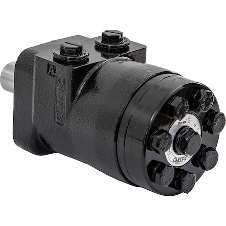
Hydraulic Motors from Buyers Products are designed to be economical, efficient, compact and powerful. They are a great solution for powering medium-duty applications like compressors, augers, winches, cranes, and spreaders. The motors have an industry-proven spool valve design combined with state-of-the-art gerotors. They excel at jobs that need a high degree of start-up torque or just the right mixture of torque and flow rate. Choose from a wide range of motors depending on your needs for flow rates, torque and starting torque. Each model is available with either a 2-bolt or 4-bolt mount. The last digit of the part number (2 or 4) will indicate the number of bolts.
Specifications
| Compares To | 101-1001-009 |
|---|---|
| Displacement | 3.1 |
| Flow (Continuous) | 12 |
| Flow (Intermittent) | 14 |
| Input Mount Type | 4 Bolt |
| Material | Cast Iron |
| Maximum Case Pressure (Without Case Drain) | 1500 |
| Maximum Speed (Continuous) | 969 |
| Maximum Speed at Continuous Flow | 969 |
| Maximum Speed at Intermittent Flow | 1130 |
| Minimum Starting Torque (Continuous Pressure) | 520 |
| Minimum Starting Torque (Intermittent Pressure) | 720 |
| Pilot Diameter | 1.75 |
| Port Size | 1/2 NPT |
| Pressure ? Bar (Continuous) | 1800 |
| Pressure ? Bar (Intermittent) | 2400 |
| Shaft Size | 1.00 |
| Shaft Type | Straight/Cross Drilled |
| Torque Rating (Continuous) | 650 |
| Torque Rating (Intermittent) | 720 |
Advanced Technical Overview: Hydraulic Motor with 4-Bolt Mount, NPT Threads, and 3.1 Cubic Inches Displacement
This detailed description expands upon the capabilities and technical specifications of the Hydraulic Motor from Buyers Products, a robust solution engineered for demanding medium-duty applications. While the product title indicates a 2.8 cubic inch displacement, the specific model detailed in the accompanying specifications table exhibits a nominal displacement of 3.1 cubic inches (ci). This technical exposition will focus on the characteristics and performance metrics inherent to this 3.1 ci variant, providing an in-depth understanding of its design, operation, and application suitability.
Core Design Principles: Gerotor Technology and Spool Valve Integration
At the heart of this hydraulic motor’s exceptional performance lies its sophisticated internal design, combining state-of-the-art gerotor technology with a precision-engineered spool valve. This configuration is widely recognized in the hydraulic industry for its ability to deliver high torque at low speeds, smooth operation, and reliable power transfer.
Understanding Gerotor Mechanisms
A gerotor, derived from "generated rotor," is a positive displacement pump or motor component comprising an inner rotor and an outer rotor. The inner rotor typically has one less lobe (or tooth) than the outer rotor. As the inner rotor rotates eccentrically within the outer rotor, it creates expanding and contracting chambers. Hydraulic fluid is drawn into the expanding chambers and expelled from the contracting chambers, converting hydraulic energy into mechanical rotational energy. The specific gerotor design utilized in this motor offers several intrinsic advantages:
- High Torque Density: Gerotor motors are renowned for their ability to generate significant torque relative to their physical size, making them ideal for applications requiring substantial rotational force from a compact package.
- Smooth Operation: The continuous meshing action of the gerotor gears minimizes pressure ripple and flow pulsations, resulting in exceptionally smooth and consistent output rotation, even at very low speeds. This characteristic is crucial for applications demanding precise control and reduced vibration.
- Durability and Longevity: With fewer moving parts compared to some other motor types and a robust material construction (cast iron), gerotor motors offer excellent wear resistance and a long operational lifespan, even under arduous conditions.
- Efficiency: The design minimizes internal leakage and optimizes fluid pathing, contributing to a high level of volumetric and mechanical efficiency across a broad operating range.
The Role of the Spool Valve Design
Complementing the gerotor mechanism is an industry-proven spool valve design. The spool valve acts as the distribution system for the hydraulic fluid, precisely directing the pressurized fluid to the appropriate chambers of the gerotor set at the correct timing. This synchronized fluid management is critical for the motor's operation, influencing its efficiency, starting torque, and overall dynamic response. Key aspects of the integrated spool valve include:
- Precise Timing: The spool valve ensures that fluid is directed to and from the gerotor chambers at the optimal points in their rotation cycle, maximizing the pressure differential across the gears and, consequently, the output torque.
- Optimized Flow Path: The design of the spool valve minimizes flow restrictions and turbulence, reducing energy losses and contributing to the motor's overall efficiency.
- Enhanced Starting Performance: A well-designed spool valve is integral to the motor's ability to generate high starting torque, as it ensures immediate and effective fluid distribution to overcome static loads.
Detailed Performance Characteristics and Specifications Analysis
The specifications table provides a comprehensive insight into the operational envelopes and performance metrics of this hydraulic motor. Understanding these parameters is essential for proper system integration and application matching.
Displacement: 3.1 Cubic Inches
The volumetric displacement of 3.1 cubic inches (ci) defines the volume of fluid required to complete one full revolution of the motor shaft. This fundamental parameter dictates the motor's speed for a given flow rate and its torque output for a given pressure. A larger displacement generally means higher torque at lower speeds for the same pressure, while a smaller displacement results in higher speeds for the same flow. For this 3.1 ci motor, it signifies a balanced design capable of delivering substantial torque for medium-duty tasks without excessively high flow requirements.
Flow Rates: 12 GPM (Continuous) / 14 GPM (Intermittent)
The specified flow rates indicate the volume of hydraulic fluid that can be continuously (12 GPM) or intermittently (14 GPM) supplied to the motor for optimal performance. Continuous flow refers to the flow rate the motor can sustain indefinitely without overheating or excessive wear, while intermittent flow represents a higher flow rate that can be handled for limited durations. These figures are critical for sizing the hydraulic pump in the system and ensuring that the motor operates within its recommended parameters. Higher flow rates directly translate to higher potential output speeds, assuming constant displacement.
Pressure Ratings: 1800 PSI (Continuous) / 2400 PSI (Intermittent)
The pressure ratings, interpreted as PSI despite the table's "Bar" notation due to the magnitudes provided, are paramount for understanding the motor's force-generating capabilities. The continuous pressure of 1800 PSI is the maximum system pressure that the motor can withstand and operate efficiently under sustained conditions. The intermittent pressure of 2400 PSI allows for short periods of higher pressure operation to overcome temporary peak loads or resistance. Operating within these pressure limits is crucial for preventing structural fatigue, leakage, and premature failure of the motor and associated hydraulic components. Higher pressure directly contributes to higher output torque for a given displacement.
Speed Ratings: 969 RPM (Continuous) / 1130 RPM (Intermittent)
The maximum speed ratings correspond to the rotational speed of the output shaft. At a continuous flow of 12 GPM and a displacement of 3.1 ci, the theoretical continuous speed is approximately 969 RPM. Similarly, with an intermittent flow of 14 GPM, the motor can reach up to 1130 RPM intermittently. These speeds are derived from the relationship: Speed (RPM) = (Flow (GPM) * 231) / Displacement (ci). These figures confirm the motor's capability to deliver suitable rotational speeds for various applications, from slower, high-torque operations like augers to moderately faster applications such as winches.
Torque Ratings: 650 lb-in (Continuous) / 720 lb-in (Intermittent)
Output torque is the most direct measure of the motor's ability to perform work. The continuous torque rating of 650 lb-in indicates the rotational force the motor can consistently deliver. The intermittent torque of 720 lb-in provides a temporary surge in power for overcoming transient overloads. These torque figures are directly proportional to the system pressure and motor displacement, minus any mechanical losses. For context, 650 lb-in is approximately 54.17 lb-ft, a substantial amount of turning force for its size, making it highly effective for driving medium-duty machinery.
Minimum Starting Torque: 520 lb-in (Continuous Pressure) / 720 lb-in (Intermittent Pressure)
A critical characteristic highlighted in the existing description is the motor's exceptional starting torque. This specification measures the minimum torque available at initial rotation, often lower than running torque due to static friction and internal inefficiencies at zero speed. With 520 lb-in at continuous pressure and 720 lb-in at intermittent pressure, this motor demonstrates a strong capability to overcome significant static loads from a standstill. This is especially vital for applications like augers and winches that frequently start under heavy load conditions, preventing stalling and ensuring reliable operation from the moment power is applied.
Maximum Case Pressure (Without Case Drain): 1500 PSI
The maximum case pressure without a case drain indicates the pressure limit within the motor housing. In motors without an external case drain port, internal leakage is directed back to the motor's outlet. A 1500 PSI limit without a case drain suggests a robust internal sealing design that can tolerate relatively high back pressure. However, for applications where back pressure might exceed this or where sustained high pressures are expected, employing an external case drain to relieve internal pressure build-up and extend seal life is generally recommended practice, if the motor design allows or provides for such a port (not explicitly stated for this model, but a general hydraulic engineering consideration).
Mechanical and Structural Attributes
Beyond its internal hydraulic mechanisms, the physical attributes of the motor are designed for robust integration and longevity.
Input Mount Type: 4-Bolt Mount
The 4-bolt mount is a common and highly robust mounting standard in the hydraulic industry. It provides a secure and stable connection between the motor and the driven machinery or mounting bracket. The symmetrical bolt pattern distributes mounting forces evenly, minimizing stress concentrations and ensuring precise alignment, which is crucial for efficient power transfer and extended bearing life. This type of mount is suitable for applications where vibration, shock loads, or high torque reactions are anticipated.
Port Size: 1/2 NPT Threads
The 1/2 NPT (National Pipe Taper) threaded ports are a widely used standard for hydraulic connections. NPT threads are designed to create a seal by the wedging action of the tapered threads, which deform slightly when tightened, ensuring a leak-tight connection, especially when used with an appropriate sealant. The 1/2-inch size is suitable for the flow rates and pressures this motor is designed to handle, balancing flow capacity with compact fitting requirements. Correctly installed NPT fittings contribute significantly to the overall integrity and leak prevention of the hydraulic system.
Shaft Size and Type: 1.00 inch Straight/Cross Drilled
The 1.00-inch straight shaft is a robust output interface, capable of transmitting the motor's full torque capacity. Straight shafts are generally designed for applications where a keyed or splined connection is made directly to the driven component, offering simplicity and strength. The "cross-drilled" feature often implies a provision for a set screw, roll pin, or similar fastening mechanism, enabling a positive lock between the shaft and the driven component (e.g., a sprocket, pulley, or coupling) to prevent slippage under torque and accommodate axial loads. This design ensures reliable power transmission to the connected load.
Pilot Diameter: 1.75 Inches
The pilot diameter is a precision-machined cylindrical boss on the motor's mounting face. Its purpose is to accurately center the motor within a mating bore on the driven equipment or mounting plate. A 1.75-inch pilot diameter ensures precise alignment, minimizing radial loads on the shaft and bearings, which is vital for smooth operation, reduced wear, and extended component life. Proper piloting is essential for the long-term reliability of any rotating machinery.
Material: Cast Iron
The use of cast iron for the motor housing is a testament to its robust and industrial-grade construction. Cast iron offers several advantages in hydraulic motor applications:
- High Strength and Rigidity: It provides excellent structural integrity, capable of withstanding the internal hydraulic pressures and external mechanical stresses.
- Vibration Damping: Cast iron has inherent damping properties, which help to absorb and dissipate vibrations generated during operation, contributing to smoother, quieter performance and reduced wear on associated components.
- Thermal Stability: It maintains its mechanical properties well across a range of operating temperatures, crucial for hydraulic systems that can generate significant heat.
- Wear Resistance: Cast iron provides good wear resistance for internal components, contributing to the motor's longevity.
- Cost-Effectiveness: It offers a balance of performance and manufacturing cost, contributing to the motor's overall economic value.
Versatile Applications: Expanding on Medium-Duty Capabilities
The inherent characteristics of this hydraulic motor – high starting torque, smooth operation, and durable construction – make it exceptionally well-suited for a broad spectrum of medium-duty applications, as initially outlined:
- Compressors: In mobile or stationary hydraulic compressor drive systems, the motor provides reliable, consistent rotational input, maintaining the necessary speed for efficient air compression. Its high starting torque assists in overcoming the initial resistance of a static compressor.
- Augers: For earth-drilling augers, post-hole diggers, or grain augers, the motor's ability to deliver high torque at low speeds and its robust starting torque are paramount for penetrating various materials and handling shock loads from obstacles or dense media.
- Winches: Winching operations demand precise control, high pulling force, and the ability to hold a load. This motor's continuous and intermittent torque ratings, coupled with its smooth operation, enable controlled lifting and lowering, while its robust construction ensures durability under load.
- Cranes: In smaller crane systems or for specific functions within larger cranes (e.g., slewing, hoist drive for lighter loads), the motor provides the necessary power and controlled motion for safe and efficient load handling.
- Spreaders: For agricultural, salt, or aggregate spreaders, the motor's consistent torque and speed help ensure uniform material distribution, even with varying material densities or flow rates, contributing to operational efficiency and reducing material waste.
Beyond these primary examples, this motor's characteristics extend its suitability to other industrial and mobile hydraulic systems, including:
- Conveyors: Driving conveyor belts in material handling systems where precise speed control and consistent torque are needed to move various goods.
- Sweepers: Powering brushes or collection mechanisms in municipal or industrial sweepers, requiring robust and continuous operation.
- Agricultural Machinery: Integrating into seeders, fertilizer applicators, or other implements requiring reliable rotary power.
- Construction Equipment Attachments: Such as trenchers, post drivers, or compactors where high torque and durability are key.
System Integration and Operational Considerations
For optimal performance and longevity, proper integration of this hydraulic motor into a complete hydraulic system is crucial. This involves careful consideration of several factors:
- Hydraulic Fluid Selection: Using the correct type and viscosity of hydraulic fluid, as specified by industry standards or manufacturer recommendations, is essential for lubrication, heat dissipation, and efficient power transmission.
- Filtration: Implementing a robust filtration system (return line filters, pressure line filters) is vital to protect the motor and other hydraulic components from contamination, which is a leading cause of hydraulic system failure.
- Heat Management: While efficient, all hydraulic systems generate some heat. Ensuring adequate reservoir size and, if necessary, a hydraulic cooler will maintain fluid temperature within optimal operating limits, preserving component life and fluid integrity.
- Line Sizing: Proper sizing of hydraulic lines (hoses and pipes) is necessary to minimize pressure drops and ensure adequate flow to the motor without excessive fluid velocity, which can lead to noise and heat.
- Pump Compatibility: The hydraulic pump chosen must be capable of supplying the continuous and intermittent flow and pressure required by the motor, with sufficient reserve for other system components.
- Relief Valves: Incorporating appropriate pressure relief valves in the hydraulic circuit is critical to protect the motor and other components from overpressure conditions.
Conclusion: A Robust and Economical Power Solution
The Hydraulic Motor from Buyers Products, specifically the 3.1 cubic inch displacement model with a 4-bolt mount and 1/2 NPT threads, represents an expertly engineered solution for a diverse range of medium-duty applications. Its fusion of an industry-proven spool valve with state-of-the-art gerotor technology ensures economical, efficient, compact, and powerful operation. With high continuous and intermittent torque ratings, robust starting torque, and durable cast iron construction, it is designed to deliver reliable performance under challenging conditions. The detailed specifications affirm its capability to provide consistent power for applications demanding precision, strength, and longevity, making it a valuable asset for engineers and operators seeking a high-performance hydraulic drive solution.