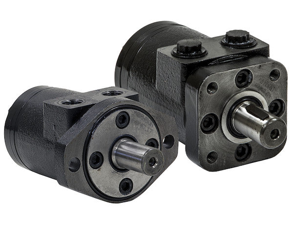
Hydraulic Motors from Buyers Products are designed to be economical, efficient, compact and powerful. They are a great solution for powering medium-duty applications like compressors, augers, winches, cranes, and spreaders. The motors have an industry-proven spool valve design combined with state-of-the-art gerotors. They excel at jobs that need a high degree of start-up torque or just the right mixture of torque and flow rate. Choose from a wide range of motors depending on your needs for flow rates, torque and starting torque. Each model is available with either a 2-bolt or 4-bolt mount. The last digit of the part number (2 or 4) will indicate the number of bolts.
Specifications
| Compares To | 101-1004-009 |
|---|---|
| Displacement | 9.6 |
| Flow (Continuous) | 15 |
| Flow (Intermittent) | 20 |
| Input Mount Type | 4 Bolt |
| Material | Cast Iron |
| Maximum Case Pressure (Without Case Drain) | 1500 |
| Maximum Speed (Continuous) | 353 |
| Maximum Speed at Continuous Flow | 353 |
| Maximum Speed at Intermittent Flow | 471 |
| Minimum Starting Torque (Continuous Pressure) | 1650 |
| Minimum Starting Torque (Intermittent Pressure) | 2320 |
| Pilot Diameter | 1.75 |
| Port Size | 1/2 NPT |
| Pressure ? Bar (Continuous) | 1650 |
| Pressure ? Bar (Intermittent) | 2250 |
| Shaft Keyway | 0.25 |
| Shaft Size | 1.00 |
| Shaft Type | Straight |
| Torque Rating (Continuous) | 2059 |
| Torque Rating (Intermittent) | 2320 |
Advanced Technical Overview: Hydraulic Motor with 4-Bolt Mount, NPT Threads, and 9.7 Cubic Inches Displacement
This detailed exposition provides a comprehensive technical analysis of the hydraulic motor featuring a 4-bolt mount, NPT threads, and a nominal displacement of 9.7 cubic inches per revolution (CIR), specifically referencing the provided specifications where the displacement is noted as 9.6 CIR. Engineered by Buyers Products, this series of hydraulic motors is meticulously designed to deliver an optimal balance of economy, efficiency, compactness, and robust power delivery. It represents an exemplary solution for a diverse array of medium-duty applications that demand reliable and consistent hydraulic power, such as actuating compressors, driving augers, operating winches, controlling crane movements, and powering material spreaders. The motor's inherent design, combining an industry-proven spool valve mechanism with cutting-edge gerotor technology, positions it as a superior choice for tasks requiring substantial start-up torque and precise control over the interplay between torque and flow rate.
Core Operating Principle: Gerotor Technology and Spool Valve Design
At the heart of this hydraulic motor’s exceptional performance lies its sophisticated internal mechanism, specifically the integration of state-of-the-art gerotor gearing with an industry-proven spool valve design.
Gerotor Mechanism:
A gerotor (generated rotor) is a positive displacement pumping unit comprising an inner rotor and an outer rotor. The inner rotor, typically with N teeth, meshes with the outer rotor, which has N+1 teeth. This unique epicyclic gearing arrangement creates expanding and contracting chambers as the rotors turn. In a hydraulic motor, high-pressure hydraulic fluid is directed into the expanding chambers, exerting force on the inner rotor and causing it to rotate. As the rotor turns, the chambers contract, expelling the lower-pressure fluid to the return line. This design inherently offers several significant advantages:
- High Efficiency: The precise meshing of the gerotor elements minimizes internal leakage, leading to superior volumetric and mechanical efficiency, especially at lower speeds.
- Smooth Operation: The continuous engagement of the rotor teeth ensures a smooth, ripple-free output torque, crucial for applications requiring precise control and minimal vibration.
- High Starting Torque: Gerotor motors are renowned for their excellent starting torque characteristics. This is vital for applications like augers and winches that need significant initial force to overcome static loads. The motor's specification of 1650 in-lbs (continuous pressure) and 2320 in-lbs (intermittent pressure) for minimum starting torque directly attests to this capability.
- Compactness: The integrated nature of the gerotor design allows for a remarkably high power-to-weight ratio, facilitating compact motor dimensions suitable for constrained installation spaces.
- Durability: With fewer moving parts compared to some other hydraulic motor types and a robust cast iron construction, gerotor motors offer exceptional longevity and reliability in demanding operational environments.
- Low Noise Levels: The inherent smooth operation and effective fluid sealing contribute to reduced noise generation during operation.
Spool Valve Design:
Complementing the gerotor mechanism is an industry-proven spool valve. This valve system is responsible for precisely directing the flow of hydraulic fluid into and out of the gerotor chambers. The spool valve acts as the control element, timing the fluid ingress and egress to optimize the torque generation and rotational speed. Its proven design ensures:
- Precise Control: Accurate fluid distribution allows for fine control over motor speed and direction.
- Enhanced Efficiency: Minimizes pressure drop across the valve, contributing to overall system efficiency.
- Reliability: A well-established design means robust performance and extended operational life, reducing maintenance requirements.
- Optimized Performance: The spool valve synchronizes fluid delivery with the gerotor's rotation, enabling the motor to deliver the specified flow rates, torque, and particularly the high starting torque, making it ideal for applications requiring instantaneous power delivery.
Displacement and Performance Characteristics
The specified displacement of 9.7 cubic inches per revolution (CIR) (or 9.6 CIR as per detailed specifications) is a critical parameter defining the motor's performance envelope. Displacement refers to the theoretical volume of hydraulic fluid required to rotate the motor output shaft one complete revolution. This value directly influences the motor's speed, torque output, and overall power generation when combined with system flow and pressure.
Flow Rates:
- Continuous Flow: Rated at 15 gallons per minute (GPM). This is the maximum flow rate the motor can sustain indefinitely without detrimental effects on its lifespan or performance.
- Intermittent Flow: Rated at 20 GPM. This flow rate can be tolerated for short durations, allowing for peak performance during demanding cycles, such as initial startup or periods of high load.
Speed Performance:
The interaction of displacement and flow rate dictates the motor's rotational speed (RPM). Using the formula RPM = (Flow Rate in GPM * 231) / Displacement in CIR:
- Maximum Speed (Continuous): With a continuous flow of 15 GPM and a displacement of 9.6 CIR, the theoretical speed is (15 * 231) / 9.6 = 360.9 RPM. The specified 353 RPM is consistent with practical operational efficiencies and safety margins.
- Maximum Speed (Intermittent): At an intermittent flow of 20 GPM, the theoretical speed is (20 * 231) / 9.6 = 481.25 RPM. The specified 471 RPM again reflects real-world operational parameters. These speeds demonstrate the motor's capability to deliver effective rotational power across its operational range.
Pressure Ratings:
While the specification table lists "Pressure ? Bar", the values of 1650 and 2250 are typical for Pounds per Square Inch (PSI) in hydraulic systems, especially in the context of the calculated torque values. Assuming these are PSI ratings:
- Continuous Pressure: 1650 PSI. This is the maximum sustained pressure the motor can operate under continuously.
- Intermittent Pressure: 2250 PSI. This higher pressure can be applied for limited durations, providing a temporary boost in torque for overcoming challenging loads.
Torque Output:
Torque is directly proportional to pressure and displacement. The motor's ability to generate high torque is a hallmark of its design, particularly critical for applications requiring significant rotational force. The torque output is typically calculated by Torque (in-lbs) = (Pressure in PSI * Displacement in CIR) / (2 * π * Efficiency).
- Torque Rating (Continuous): 2059 in-lbs. Achieved at the continuous pressure and flow, demonstrating robust and sustained power.
- Torque Rating (Intermittent): 2320 in-lbs. This higher intermittent torque allows the motor to handle transient peak loads, further extending its versatility.
- Minimum Starting Torque: The values of 1650 in-lbs (continuous pressure) and 2320 in-lbs (intermittent pressure) for starting torque underscore the motor's immediate responsiveness and power from a standstill, which is crucial for applications like augers and winches that encounter high initial resistance.
Mounting Configuration: 4-Bolt Mount
This particular hydraulic motor is equipped with a 4-bolt mount, a widely adopted standard in industrial and mobile hydraulic systems, offering superior stability and load distribution compared to its 2-bolt counterparts. The 4-bolt mount provides several distinct advantages:
- Enhanced Stability: With attachment points symmetrically distributed around the motor's mounting face, the 4-bolt configuration ensures a more rigid and secure connection to the driven equipment or mounting bracket. This stability is crucial in applications experiencing high torque, vibration, or shock loads.
- Superior Force Distribution: The four bolts distribute the operational stresses, including radial and axial loads, more evenly across the mounting surface. This minimizes localized stress concentrations, reduces wear on components, and extends the overall life of both the motor and the driven equipment.
- Reduced Vibration and Noise: A more secure mount effectively dampens vibrations generated during motor operation, contributing to quieter running and less fatigue on the connected machinery.
- Precise Alignment: The 1.75-inch pilot diameter, combined with the 4-bolt pattern, facilitates accurate alignment between the motor shaft and the driven component. Precise alignment is paramount for preventing premature bearing wear, coupling failure, and inefficiencies in power transmission.
- Increased Load-Bearing Capacity: The robust nature of the 4-bolt mount makes it suitable for applications where the motor is subjected to higher external forces or where the driven load is substantial, typical for medium-duty winches, augers, and cranes.
The choice of a 4-bolt mount signifies the motor's suitability for more demanding applications where mechanical integrity and reliable power transmission are non-negotiable.
Porting Standard: NPT Threads
The motor features 1/2 NPT (National Pipe Taper) threaded ports, a ubiquitous standard for connecting hydraulic lines in North America and beyond. NPT threads are distinguished by their tapered profile, which creates a metal-to-metal seal as the male and female threads are tightened. While often supplemented with thread sealant for optimal leak prevention, the tapered design provides a mechanically robust and secure connection. The use of 1/2 NPT ports offers:
- Widespread Availability: NPT fittings and adapters are readily available globally, simplifying system integration, maintenance, and replacement.
- Reliable Sealing: When properly installed with an appropriate thread sealant, NPT connections offer excellent resistance to leaks, critical for maintaining hydraulic system integrity and efficiency.
- Cost-Effectiveness: Due to their commonality, NPT fittings are generally more economical than specialized hydraulic connection types, reducing overall system cost.
- Adequate Flow Capacity: The 1/2 NPT port size is well-suited for the motor's specified continuous flow of 15 GPM and intermittent flow of 20 GPM, minimizing pressure drops across the ports and ensuring efficient fluid transfer.
Construction Material: Cast Iron Durability
The motor housing is constructed from high-quality cast iron, a material specifically chosen for its exceptional mechanical properties and suitability for hydraulic components. Cast iron offers a compelling array of benefits that contribute to the motor's longevity and performance:
- High Compressive Strength: Cast iron exhibits superior resistance to compressive forces, enabling the motor to withstand the high internal pressures inherent in hydraulic systems (up to 2250 PSI intermittent).
- Excellent Damping Characteristics: Its inherent microstructure provides excellent vibration and noise damping capabilities, contributing to smoother, quieter operation and reduced wear on internal components. This is a significant advantage in applications where noise reduction is a factor.
- Wear Resistance: Cast iron offers good wear resistance, particularly when lubricated by hydraulic fluid, ensuring the longevity of critical mating surfaces and reducing internal leakage over time.
- Thermal Stability: It maintains its mechanical properties across a wide range of operating temperatures, crucial for hydraulic systems that can experience significant heat generation.
- Rigidity and Stability: The stiffness of cast iron provides a highly stable platform for the internal gerotor and spool valve components, maintaining tight tolerances and maximizing efficiency throughout the motor's operational life.
- Corrosion Resistance: While not fully impervious, cast iron provides reasonable resistance to corrosion in typical hydraulic fluid environments, especially when fluids are properly maintained.
The use of cast iron underscores the motor's design for robust and reliable performance in challenging industrial and mobile environments, promising extended service life and reduced total cost of ownership.
Shaft Characteristics: Straight with Keyway
The motor features a straight output shaft with a 1.00-inch diameter and a 0.25-inch keyway. This shaft configuration is a standard and highly practical choice for mechanical power transmission:
- Straight Shaft: Simplicity and ease of coupling are primary benefits. Straight shafts readily interface with a wide range of standard couplings, gearboxes, and pulleys.
- 1.00-inch Diameter: This dimension provides adequate torsional strength to transmit the motor's substantial continuous (2059 in-lbs) and intermittent (2320 in-lbs) torque ratings without excessive stress or deformation.
- 0.25-inch Keyway: The keyway is a slot cut into the shaft that accommodates a rectangular key. This key then fits into a corresponding keyway in the hub of the driven component (e.g., a sprocket, pulley, or coupling). The key and keyway system is a highly effective method for transmitting torque from the motor shaft to the driven component, preventing relative rotation between the two parts. It is simple, reliable, and widely used across various mechanical drive systems.
This shaft configuration ensures secure and efficient transfer of rotational power to the application, minimizing slippage and maximizing mechanical efficiency.
Application Versatility for Medium-Duty Operations
This hydraulic motor is engineered to excel in a variety of medium-duty applications, where its unique combination of high starting torque, robust construction, and efficient power delivery provides significant operational advantages:
- Compressors: Provides consistent rotational input for hydraulic-driven air compressors, ensuring stable air supply for pneumatic tools and systems.
- Augers: The high minimum starting torque (up to 2320 in-lbs) is crucial for driving augers in earthmoving, agricultural, or construction applications, allowing them to effectively break through compacted soil or material from a standstill.
- Winches: Essential for winching operations, where high torque is needed to initiate pulling heavy loads and maintain consistent speed under varying resistance. The motor's robust design ensures reliable operation under the high stresses common in winching.
- Cranes: Offers the necessary torque and controlled speed for slewing, hoisting, or telescoping functions in small to medium-sized cranes, enabling precise load positioning and smooth movements.
- Spreaders: Whether for salt, sand, gravel, or agricultural products, this motor provides the dependable power required to drive spreader mechanisms, ensuring even and consistent material distribution.
Beyond these specific examples, its specifications make it suitable for various agricultural machinery (e.g., conveyor drives, harvesting equipment), construction equipment (e.g., small trenchers, post-hole diggers), and other industrial machinery demanding reliable medium-range hydraulic power.
System Integration and Operational Considerations
Integrating this hydraulic motor into an existing or new system requires attention to several design and operational parameters to maximize its performance and lifespan:
- Hydraulic Fluid: Selection of the correct hydraulic fluid is paramount. It must meet OEM specifications for viscosity, lubricity, and thermal stability to ensure optimal motor performance, internal component lubrication, and heat dissipation.
- Filtration: Proper fluid filtration is critical. Contaminants are the leading cause of hydraulic component failure. The system should incorporate appropriate filtration levels to protect the sensitive gerotor and spool valve components from wear.
- Pressure Relief: Implementing correctly sized and set pressure relief valves is essential to protect the motor and the entire hydraulic circuit from over-pressurization, particularly during intermittent peak loads.
- Case Drain (if applicable): While the motor specifies a maximum case pressure of 1500 PSI without a case drain, for applications with very high intermittent pressures or extended duty cycles, considering a case drain line can help manage internal pressure build-up and extend seal life.
- Thermal Management: Maintaining hydraulic fluid within an optimal temperature range is vital. Excessive heat can degrade fluid properties and damage seals. System design should include adequate cooling if necessary.
- Maintenance: Regular inspection of hydraulic lines, fittings, and seals, along with scheduled fluid changes and filter replacements, will ensure the motor operates efficiently and reliably for its intended service life.
Conclusion
The Hydraulic Motor with a 4-bolt mount, NPT threads, and a 9.7 (or 9.6) cubic inches displacement from Buyers Products stands as a robust, efficient, and versatile solution for a broad spectrum of medium-duty hydraulic applications. Its meticulously engineered design, centered on an advanced gerotor mechanism and a proven spool valve, ensures high starting torque, smooth operation, and reliable power delivery. The specific configuration, featuring a strong cast iron construction, a stable 4-bolt mount, and user-friendly NPT ports, positions it as a highly durable and easily integrable component. With its precise control over torque and flow, this motor is an indispensable asset for equipment ranging from essential agricultural machinery to demanding construction and utility vehicles, guaranteeing economical and powerful performance where it matters most.