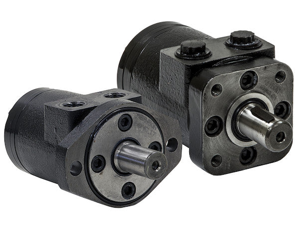
Hydraulic Motors from Buyers Products are designed to be economical, efficient, compact and powerful. They are a great solution for powering medium-duty applications like compressors, augers, winches, cranes, and spreaders. The motors have an industry-proven spool valve design combined with state-of-the-art gerotors. They excel at jobs that need a high degree of start-up torque or just the right mixture of torque and flow rate. Choose from a wide range of motors depending on your needs for flow rates, torque and starting torque. Each model is available with either a 2-bolt or 4-bolt mount. The last digit of the part number (2 or 4) will indicate the number of bolts.
Specifications
| Compares To | 101-1032-009 |
|---|---|
| Displacement | 23.7 |
| Flow (Continuous) | 15 |
| Flow (Intermittent) | 20 |
| Input Mount Type | 2 Bolt |
| Material | Cast Iron |
| Maximum Case Pressure (Without Case Drain) | 1500 |
| Maximum Speed (Continuous) | 192 |
| Maximum Speed at Continuous Flow | 192 |
| Maximum Speed at Intermittent Flow | 203 |
| Minimum Starting Torque (Continuous Pressure) | 2920 |
| Minimum Starting Torque (Intermittent Pressure) | 3610 |
| Pilot Diameter | 3.25 |
| Port Size | 1/2 NPT |
| Pressure ? Bar (Continuous) | 1250 |
| Pressure ? Bar (Intermittent) | 1500 |
| Shaft Keyway | 0.25 |
| Shaft Size | 1.00 |
| Shaft Type | Straight |
| Torque Rating (Continuous) | 3110 |
| Torque Rating (Intermittent) | 3610 |
Advanced Technical Overview: Hydraulic Motor With 2-Bolt Mount/NPT Threads And 22.6 Cubic Inches Displacement
This detailed technical description provides an in-depth analysis of the Hydraulic Motor from Buyers Products, a robust and efficient solution engineered for demanding medium-duty applications. With a nominal displacement of 22.6 cubic inches (as per title, or 23.7 cubic inches as per detailed specifications), a standardized 2-bolt mount, and versatile NPT threads, this motor is designed to deliver reliable hydraulic power with exceptional performance characteristics. It embodies a sophisticated fusion of proven hydraulic principles and advanced manufacturing techniques, making it an indispensable component for a wide array of industrial and mobile hydraulic systems.
Fundamental Principles of Hydraulic Motor Operation
A hydraulic motor converts hydraulic energy (fluid flow and pressure) into mechanical energy (rotary motion and torque). This conversion is achieved through a precise internal mechanism that interacts with the pressurized hydraulic fluid. Compared to electric or pneumatic motors, hydraulic motors offer superior power density, allowing for compact designs that deliver substantial torque. Key advantages include smooth and continuous operation, precise speed and torque control, rapid reversibility, and high starting torque capabilities, all critical for the demanding applications this motor is designed to serve.
Mechanical Design and Integration Features
Robust 2-Bolt Mount Configuration
The motor features a standardized 2-bolt mount, specifically designed for secure and stable integration into various machinery and equipment. This mounting standard, typically conforming to SAE (Society of Automotive Engineers) specifications, ensures compatibility with a broad range of hydraulic pumps, gearboxes, and other system components. The 2-bolt configuration is renowned for its strength and reliability, providing a rigid connection that can withstand the dynamic forces and vibrations inherent in hydraulic operations. The specified Pilot Diameter of 3.25 inches is crucial for concentric alignment, ensuring the motor shaft is perfectly centered with the driven component, thereby minimizing misalignment stresses, reducing wear on bearings and seals, and maximizing the operational lifespan of the system. This precise alignment contributes significantly to the motor's overall efficiency and reduced maintenance requirements.
National Pipe Taper (NPT) Threads for Secure Connections
Equipped with 1/2 NPT (National Pipe Taper) port threads, this hydraulic motor ensures robust and leak-resistant connections for hydraulic lines. NPT threads are a widely adopted standard in North America for their inherent ability to create a pressure-tight seal without the need for additional O-rings, relying instead on the taper and interference fit between the male and female threads. When properly installed with an appropriate thread sealant, NPT connections offer a highly dependable interface, crucial for maintaining system integrity and preventing fluid loss in high-pressure hydraulic environments. The 1/2 NPT size denotes a port suitable for moderate flow rates (up to 20 GPM intermittent), correlating perfectly with the motor's displacement and application profile, facilitating efficient fluid transfer to and from the power unit.
Durable Cast Iron Construction
The selection of cast iron as the primary material for the motor housing is a deliberate engineering choice that underscores durability and performance. Cast iron possesses exceptional mechanical properties vital for hydraulic components:
- High Strength: It offers superior compressive and tensile strength, allowing the motor to withstand the high internal pressures and external stresses typical in hydraulic systems.
- Vibration Damping: Cast iron exhibits excellent inherent vibration damping characteristics, contributing to smoother operation and reduced noise levels, which in turn enhances component longevity.
- Heat Dissipation: Its thermal conductivity aids in dissipating heat generated during operation, preventing thermal degradation of hydraulic fluid and internal components.
- Dimensional Stability: Cast iron maintains its structural integrity across a wide range of operating temperatures, ensuring consistent performance and precise internal clearances.
Precision Straight Shaft with Keyway
The motor features a 1.00-inch diameter straight shaft with a 0.25-inch keyway. This design is a standard and highly effective method for transmitting torque from the motor to the driven load. A straight shaft provides a strong and reliable interface, compatible with common couplings, pulleys, and sprockets. The keyway, a precisely machined groove, accommodates a key that locks the shaft to the connected component, preventing relative rotation and ensuring positive torque transmission. This simple yet robust mechanical interface is critical for applications requiring significant torque output and rotational stability, minimizing backlash and ensuring efficient power delivery.
Advanced Internal Mechanisms: Spool Valve and Gerotor Technology
Industry-Proven Spool Valve Design
The motor incorporates an "industry-proven spool valve design" which is central to its operational efficiency and control. Spool valves are critical components in hydraulic systems, responsible for directing the flow of hydraulic fluid, thereby controlling the motor's speed and direction. In this context, the spool valve accurately meters the flow of fluid into the gerotor element, ensuring precise control over the motor's rotational output. An established design indicates reliability, predictable performance, and ease of maintenance, building upon years of engineering refinement and field validation. This design contributes to the motor's ability to achieve "just the right mixture of torque and flow rate" for diverse operational demands.
State-of-the-Art Gerotor Technology
At the heart of this hydraulic motor lies a "state-of-the-art gerotor" (Gerotor is an acronym for "generated rotor") mechanism. Gerotor motors are a type of orbital motor characterized by an inner and outer gear set that rotates eccentrically within a housing. The inner gear has one less tooth than the outer gear, creating expanding and contracting chambers as the gears rotate. Pressurized fluid enters the expanding chambers, forcing the gears to turn, and then exits from the contracting chambers. This design offers several significant advantages:
- High Volumetric Efficiency: The tight tolerances and sealing within the gerotor set minimize internal leakage, converting a higher percentage of input flow into useful work.
- Smooth Operation: The continuous engagement of the gear teeth ensures smooth, low-ripple torque output, even at low speeds.
- Compact Design: Gerotor motors are known for their high power density, delivering substantial power within a relatively small envelope, making them ideal for applications with space constraints.
- High Starting Torque: This characteristic is a direct benefit of the gerotor's design, which allows for a large pressure area to act on the rotor from a standstill, enabling the motor to overcome high initial loads effectively. This directly addresses the motor's stated excellence in jobs needing "a high degree of start-up torque."
Detailed Performance Metrics and Their Significance
Displacement (22.6 / 23.7 Cubic Inches)
The motor's displacement, specified at 22.6 cubic inches (or 23.7 cubic inches in the detailed specifications table), is a fundamental parameter that defines its operating characteristics. Displacement refers to the theoretical volume of hydraulic fluid required for one complete revolution of the motor shaft. This value directly influences the motor's torque output and speed capabilities:
- Torque Output: For a given system pressure, a larger displacement motor will produce more torque (Torque = (Pressure * Displacement) / (2π * Efficiency)). This substantial displacement positions the motor to generate significant torque, which is essential for heavy-duty pulling, lifting, and rotary applications.
- Speed Capabilities: For a given fluid flow rate, a larger displacement motor will rotate at a lower speed (Speed = Flow Rate / Displacement). This characteristic implies that this motor is optimized for applications requiring high torque at moderate to lower RPMs, rather than high-speed, low-torque operations.
Flow Rate (Continuous: 15 GPM, Intermittent: 20 GPM)
The flow rate ratings indicate the volume of hydraulic fluid the motor can continuously or intermittently process.
- Continuous Flow (15 GPM): This is the maximum flow rate the motor can sustain for extended periods without exceeding its thermal or mechanical limits. It dictates the motor's maximum continuous operating speed for a given displacement.
- Intermittent Flow (20 GPM): This represents the maximum flow rate the motor can handle for short durations, typically up to 10% of its operating cycle. This intermittent capability allows the motor to briefly operate at higher speeds or power outputs for peak demand scenarios, such as overcoming transient overloads or accelerating a load.
Pressure Ratings (Continuous: 1250 PSI, Intermittent: 1500 PSI)
The pressure ratings are crucial for safe and effective system design:
- Continuous Pressure (1250 PSI): This is the maximum system pressure that can be continuously applied to the motor without compromising its structural integrity or expected lifespan. It forms the basis for calculating the motor's continuous torque output.
- Intermittent Pressure (1500 PSI): This denotes the maximum pressure the motor can withstand for brief periods. This intermittent capacity allows the motor to generate higher peak torque for demanding tasks like breaking static friction or handling sudden load increases.
Torque Ratings (Continuous: 3110 lb-in, Intermittent: 3610 lb-in)
These torque figures directly reflect the motor's power output capabilities:
- Continuous Torque Rating (3110 lb-in): This is the maximum torque the motor can produce and sustain indefinitely under its continuous pressure and flow ratings. It's the primary indicator of the motor's work capacity for ongoing operations.
- Intermittent Torque Rating (3610 lb-in): This represents the peak torque achievable during intermittent operation, leveraging the higher intermittent pressure rating. This capability is vital for applications requiring high initial effort or occasional overload handling.
Speed Ratings (Continuous: 192 RPM, Intermittent: 203 RPM)
The speed ratings indicate the rotational velocity of the output shaft:
- Maximum Speed (Continuous) at Continuous Flow (192 RPM): This is the maximum sustainable rotational speed corresponding to the continuous flow rate.
- Maximum Speed (Intermittent) at Intermittent Flow (203 RPM): This higher speed can be achieved during short bursts when the motor is operating at its intermittent flow capacity.
Maximum Case Pressure (Without Case Drain): 1500 PSI
The "Maximum Case Pressure (Without Case Drain)" specification is a critical detail. In many hydraulic motors, a case drain line is used to vent internal leakage fluid back to the reservoir, preventing pressure buildup within the motor housing. For this specific motor, the design allows for internal pressure up to 1500 PSI without the need for an external case drain. This simplifies hydraulic plumbing and reduces potential leak points, contributing to a cleaner and more straightforward system installation. The ability to operate without a case drain indicates a robust sealing mechanism and internal design capable of withstanding significant internal pressure variations, further enhancing its reliability and reducing installation complexity.
Application Suitability: Powering Medium-Duty Demands
The combination of high starting torque, robust construction, specific displacement, and continuous/intermittent performance envelopes makes this hydraulic motor an optimal choice for a range of medium-duty industrial and mobile applications:
- Compressors: Providing consistent, reliable power for rotary compressors in mobile or industrial settings, ensuring stable output for pneumatic tools or systems.
- Augers: Excelling in earth drilling or material mixing applications where high initial torque is required to penetrate resistant materials and maintain steady rotation under load.
- Winches: Offering controlled lifting and pulling capabilities, crucial for vehicle recovery, material handling, and marine applications, where precise speed and high torque from a standstill are paramount.
- Cranes: Facilitating the precise, smooth, and powerful rotational movements required for crane booms or hoist mechanisms, contributing to safe and efficient load manipulation.
- Spreaders: Ensuring consistent and controlled dispersal of materials such as salt, sand, or fertilizer, often in challenging environmental conditions, requiring reliable torque and speed control.
System Integration and Longevity Considerations
For optimal performance and extended lifespan, integrating this hydraulic motor into a well-designed hydraulic system is essential. This includes selecting an appropriately sized hydraulic pump to provide the necessary flow and pressure, utilizing suitable directional and pressure relief valves for control and safety, and ensuring adequate reservoir capacity for heat dissipation and fluid storage. Furthermore, strict adherence to fluid cleanliness standards through proper filtration is paramount to protect the precision internal components of the motor from abrasive wear. Regular maintenance, including hydraulic fluid quality checks and seal inspections, will ensure the motor operates within its design parameters, maximizing its reliability and minimizing downtime.
Conclusion: A Precision-Engineered Power Solution
The Hydraulic Motor with 2-Bolt Mount/NPT Threads and 22.6/23.7 Cubic Inches Displacement from Buyers Products represents a high-performance, technically advanced solution for critical medium-duty hydraulic power requirements. Its meticulous engineering, encompassing a robust cast iron construction, a precise 2-bolt mounting interface, secure NPT threaded ports, and an efficient gerotor mechanism with an industry-proven spool valve, ensures exceptional durability, efficiency, and control. With its high starting torque, balanced flow and pressure capabilities, and reliable performance envelope, this motor is not merely a component but a strategic asset, designed to enhance the productivity and longevity of any hydraulic system it powers. It stands as a testament to advanced hydraulic engineering, providing a dependable and powerful solution for the most challenging applications.