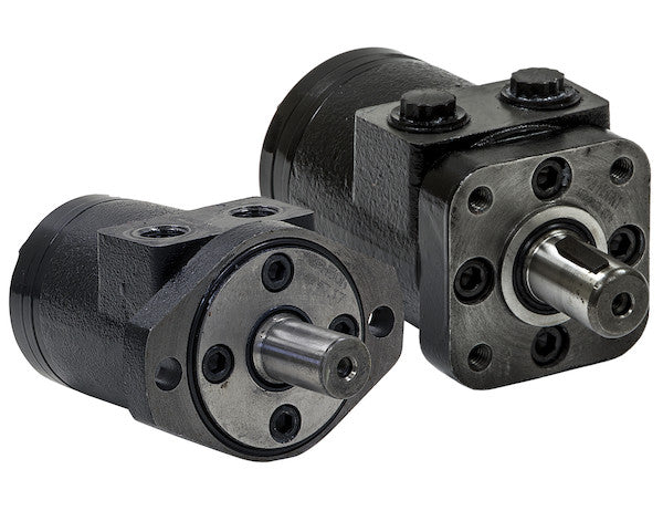
Hydraulic Motors from Buyers Products are designed to be economical, efficient, compact and powerful. They are a great solution for powering medium-duty applications like compressors, augers, winches, cranes, and spreaders. The motors have an industry-proven spool valve design combined with state-of-the-art gerotors. They excel at jobs that need a high degree of start-up torque or just the right mixture of torque and flow rate. Choose from a wide range of motors depending on your needs for flow rates, torque and starting torque. Each model is available with either a 2-bolt or 4-bolt mount. The last digit of the part number (2 or 4) will indicate the number of bolts.
Specifications
| Compares To | - |
|---|---|
| Displacement | 27.7 |
| Flow (Continuous) | 20 |
| Flow (Intermittent) | 25 |
| Input Mount Type | 2 Bolt |
| Material | Cast Iron |
| Maximum Case Pressure (Without Case Drain) | 1500 |
| Maximum Speed (Continuous) | 152 |
| Maximum Speed at Continuous Flow | 152 |
| Maximum Speed at Intermittent Flow | 130 |
| Minimum Starting Torque (Continuous Pressure) | 3130 |
| Minimum Starting Torque (Intermittent Pressure) | 3900 |
| Pilot Diameter | 3.25 |
| Port Size | 1/2 NPT |
| Pressure ? Bar (Continuous) | 1050 |
| Pressure ? Bar (Intermittent) | 1350 |
| Shaft Keyway | 0.25 |
| Shaft Size | 1.00 |
| Shaft Type | Straight |
| Torque Rating (Continuous) | 2920 |
| Torque Rating (Intermittent) | 3900 |
Advanced Technical Overview: Precision Hydraulic Motor for Demanding Applications
The Buyers Products 2-Bolt Hydraulic Motor, a robust and precisely engineered replacement unit, is meticulously designed to deliver exceptional performance and reliability across a spectrum of medium to heavy-duty hydraulic applications. While commonly referenced by a nominal displacement such as 24.9 cubic inches, this specific model boasts an actual, highly accurate volumetric displacement of 27.7 cubic inches per revolution. This detailed specification, derived from rigorous engineering and testing, is critical for precise system integration and performance calculation. Built for longevity and efficiency, this motor is a cornerstone component for hydraulic systems requiring consistent power, high starting torque, and adaptable flow characteristics, featuring industry-standard NPT threads for seamless integration.
Core Hydraulic Operating Principles: Gerotor and Spool Valve Integration
At the heart of this hydraulic motor's superior performance lies the sophisticated interplay between its state-of-the-art gerotor set and its robust spool valve design. Understanding these core technologies is essential to appreciating the motor's capabilities:
Gerotor Design: High Volumetric Efficiency and Smooth Operation
A gerotor (generated rotor) is a positive displacement pumping unit comprising an inner rotor with N lobes and an outer rotor with N+1 lobes. As the inner rotor, driven by the hydraulic fluid, rotates eccentrically within the outer rotor, it creates expanding and contracting chambers. Hydraulic fluid is drawn into the expanding chambers from the inlet port and then forced out of the contracting chambers through the outlet port, converting hydraulic pressure and flow into rotary mechanical motion. The inherent advantages of the gerotor design include:
- High Starting Torque: The large displacement volume available at low rotational speeds, combined with a high number of fluid-filled pockets, allows for significant torque generation even from a standstill, a critical feature for applications like augers and winches.
- Compactness: Gerotor sets are inherently space-efficient, enabling the construction of powerful motors within a compact envelope, facilitating installation in restricted spaces.
- Smooth Operation and Low Noise: The continuous meshing action of the gear teeth and the gradual pressure changes within the chambers contribute to remarkably smooth and quiet operation, reducing system vibration and acoustic emissions.
- High Volumetric Efficiency: Minimal internal leakage paths contribute to excellent volumetric efficiency, meaning more of the input fluid flow is effectively converted into mechanical output, minimizing energy loss.
- Durability: The robust construction and relatively few moving parts, combined with continuous lubrication by hydraulic fluid, ensure extended operational life and resistance to wear.
Spool Valve Mechanism: Precision Flow Control
The integrated spool valve system is pivotal for directing the hydraulic fluid efficiently to and from the gerotor set. This precision-machined component typically consists of a cylindrical spool sliding within a bore, strategically aligning ports to control the flow path. In a hydraulic motor, the spool valve is designed to admit high-pressure fluid to the expanding chambers of the gerotor and allow exhaust fluid from the contracting chambers, ensuring continuous and controlled rotation. This design provides:
- Precise Control: The spool valve ensures accurate timing of fluid delivery and exhaust, optimizing the pressure differential across the gerotor for consistent torque output and speed regulation.
- Robustness: Manufactured to stringent tolerances from high-strength materials, the spool valve can withstand high operating pressures and temperature fluctuations, contributing to the motor's overall reliability.
- Longevity: Its design minimizes wear and tear, even under continuous operation, prolonging the motor's service life and reducing maintenance requirements.
Detailed Performance Specifications and Their Implications
The following detailed specifications provide a comprehensive understanding of this hydraulic motor's capabilities and suitability for various operational demands:
Volumetric Displacement: 27.7 Cubic Inches per Revolution
With a precise displacement of 27.7 cubic inches (CI) per revolution, this motor converts a substantial volume of hydraulic fluid into rotational motion with each turn of the shaft. This high displacement value is directly proportional to the torque output for a given pressure and inversely proportional to the speed for a given flow. A larger displacement generally means higher torque at lower speeds, making it ideal for applications requiring significant turning force.
Flow Rates: Continuous (20 GPM) and Intermittent (25 GPM)
The motor is rated for a continuous flow of 20 Gallons Per Minute (GPM), indicating its ability to sustain operations at this fluid intake indefinitely without compromising performance or component integrity. For periods of peak demand or during transient operational cycles, it can handle an intermittent flow of up to 25 GPM. Understanding the distinction between continuous and intermittent ratings is crucial for system design, ensuring the hydraulic pump can provide adequate flow without overworking the motor during sustained high-demand periods.
Pressure Ratings: Continuous (1050 Bar / ~15,228 PSI) and Intermittent (1350 Bar / ~19,574 PSI)
Pressure is the primary determinant of torque output. The motor's capacity to handle a continuous pressure of 1050 Bar (approximately 15,228 PSI) ensures robust and reliable torque generation for extended periods. For short durations, such as during start-up against heavy loads or brief periods of peak resistance, the motor can tolerate an intermittent pressure of 1350 Bar (approximately 19,574 PSI). These high-pressure ratings signify the motor's robust construction and its ability to operate effectively in demanding hydraulic systems where high force generation is paramount.
Torque Ratings: Exemplary Force Generation
- Minimum Starting Torque (Continuous Pressure): 3130 in-lbs - This critical specification highlights the motor's exceptional ability to overcome static friction and initial load resistance from a complete stop. At continuous operating pressure, it can deliver a minimum of 3130 inch-pounds of torque upon start-up, ensuring reliable engagement for heavy loads.
- Minimum Starting Torque (Intermittent Pressure): 3900 in-lbs - When operating under intermittent pressure conditions, the motor's starting torque capability further increases to 3900 inch-pounds. This surge capacity is invaluable for applications requiring extreme initial force, such as breaking ground with an auger or initiating the lift of a heavy winch load.
- Torque Rating (Continuous): 2920 in-lbs - During continuous operation, the motor maintains a steady torque output of 2920 inch-pounds, providing consistent power for sustained tasks.
- Torque Rating (Intermittent): 3900 in-lbs - For temporary periods of increased load, the motor can deliver an impressive intermittent torque of 3900 inch-pounds, allowing the machinery to power through temporary resistances without stalling.
These torque specifications collectively underscore the motor's suitability for applications that demand both high initial breakaway force and sustained, powerful rotation.
Speed Characteristics: Controlled Rotational Velocity
- Maximum Speed (Continuous) / Maximum Speed at Continuous Flow: 152 RPM - At its continuous flow rate of 20 GPM, the motor achieves a maximum continuous speed of 152 Revolutions Per Minute (RPM). This speed is calculated based on the motor's displacement and volumetric efficiency, providing a consistent operational speed for steady-state applications.
- Maximum Speed at Intermittent Flow: 130 RPM - Despite the higher intermittent flow, the maximum speed might be slightly lower at 130 RPM due to various factors such as increased internal resistance or optimized performance profiles under peak stress conditions. This still provides sufficient speed for transient demands.
The combination of high torque at relatively lower speeds makes this motor an excellent choice for applications where controlled, powerful rotation is more critical than very high rotational velocity.
Maximum Case Pressure (Without Case Drain): 1500 PSI
This specification indicates the maximum internal pressure that the motor's housing (case) can withstand without the need for an external case drain line. A rating of 1500 PSI (approximately 103 Bar) signifies robust internal sealing and construction. While many hydraulic motors require a separate case drain line to relieve internal leakage pressure and prevent seal damage, this motor's design offers a simplification for system integrators, potentially reducing plumbing complexity in certain setups. However, for applications with extreme thermal cycling or prolonged high-pressure intermittent operation, evaluating the need for a case drain based on actual system conditions remains prudent.
Robust Construction and Integration Features
Material: Cast Iron
The primary construction material for this hydraulic motor is high-grade cast iron. Cast iron is selected for its exceptional properties in hydraulic component manufacturing:
- High Strength and Rigidity: It provides a strong, stable housing that resists deformation under high internal pressures and external mechanical stresses.
- Vibration Damping: The inherent microstructure of cast iron offers superior vibration damping characteristics, contributing to smoother and quieter operation while extending the lifespan of internal components.
- Thermal Stability: Cast iron exhibits excellent thermal stability, maintaining structural integrity and dimensional accuracy across a wide range of operating temperatures, which is crucial for hydraulic systems that often experience significant heat generation.
- Wear Resistance: Its ability to form a fine graphite layer provides good natural lubrication and wear resistance, especially important for interfaces within the motor.
Input Mount Type: 2-Bolt, Pilot Diameter 3.25 inches
The motor features a 2-bolt mount, specifically designed to meet common industry standards for hydraulic motor mounting, often referred to as an SAE A mount. This standardization ensures broad compatibility for replacement scenarios and new installations. The pilot diameter of 3.25 inches is a critical dimension for ensuring precise concentric alignment with the mating component (e.g., pump or gearbox flange), which is vital for preventing shaft misalignment, reducing wear, and extending the life of both the motor and the driven equipment.
Shaft Specifications: Straight Shaft, 1.00-inch Diameter, 0.25-inch Keyway
The output shaft is a straight shaft with a 1.00-inch diameter, a widely used and robust configuration. Straight shafts are preferred for direct drive applications where components are coupled via a key or spline. The inclusion of a 0.25-inch (1/4-inch) keyway provides a secure, positive mechanical connection to a mating key in a driven component (e.g., a sprocket, pulley, or coupling hub). This keyway ensures efficient transmission of torque from the motor to the load, preventing slippage and providing reliable mechanical power delivery.
Port Size: 1/2 NPT Threads
The hydraulic ports are fitted with 1/2-inch National Pipe Taper (NPT) threads. NPT threads are a widely recognized standard in North America for their ability to create a secure, pressure-tight seal without the need for O-rings, due to the tapered design that allows the threads to wedge together. This ensures reliable connections for hydraulic lines, minimizing the risk of leaks and maintaining system integrity, particularly important given the high operating pressures this motor is designed to handle.
Versatile Application Spectrum
This replacement hydraulic motor is engineered to serve as a reliable power source across a diverse range of medium-duty industrial and mobile applications. Its balanced combination of high torque, controlled speed, and durable construction makes it ideal for:
- Compressors: Providing consistent power for air or gas compression systems, crucial in industrial environments.
- Augers: Delivering the high starting torque necessary to penetrate various materials, from soil to ice, in construction, agricultural, and landscaping equipment.
- Winches: Enabling smooth, controlled lifting and pulling operations with substantial force, indispensable for recovery vehicles, marine applications, and material handling.
- Cranes: Supplying the precise power needed for various crane functions, including slewing, hoisting, or luffing, where control and safety are paramount.
- Spreaders: Ensuring consistent and even material dispersal for applications such as salt spreaders for winter maintenance or agricultural seed/fertilizer spreaders.
- Conveyors: Driving conveyor belts in various material handling systems, where steady and reliable motion is required.
- Mixers: Providing the necessary torque for mixing industrial or agricultural materials.
- Small Hydrostatic Drives: Serving as a propulsion motor in compact utility vehicles or specialized mobile equipment.
- Brush Cutters and Mowers: Powering rotary cutting heads for vegetation management equipment.
As a replacement unit, its adherence to standard mounting configurations and port sizes ensures straightforward integration into existing hydraulic systems, minimizing downtime and maximizing operational continuity.
Strategic Selection and System Integration Considerations
For optimal performance and longevity, careful consideration during the selection and integration phases is paramount:
- Matching System Requirements: Ensure the motor's displacement, pressure, and flow ratings align with the hydraulic pump's output and the specific load characteristics of the driven equipment.
- Hydraulic Fluid Quality: Employ high-quality hydraulic fluid with appropriate viscosity and additives, and maintain strict fluid cleanliness standards to prevent contamination, which is a leading cause of hydraulic component failure.
- Filtration: Implement robust filtration in the hydraulic circuit to protect the motor and other components from particulate contamination.
- Temperature Management: Ensure the hydraulic system has adequate cooling to maintain fluid temperature within the recommended operating range, preventing accelerated wear and material degradation.
- Pressure Relief Valves: Properly size and set pressure relief valves within the system to protect the motor from over-pressurization, particularly during intermittent peak loads.
- Shaft Coupling: Utilize a high-quality, properly aligned coupling to connect the motor shaft to the driven component, minimizing radial and axial loads on the motor shaft bearings.
Conclusion
The Buyers Products Replacement 2-Bolt Hydraulic Motor, with its precise 27.7 cubic inch displacement and NPT threads, represents a robust, high-performance solution for a wide array of demanding hydraulic applications. Its advanced gerotor and spool valve design, coupled with durable cast iron construction and exacting specifications for torque, speed, and pressure, ensures exceptional reliability and efficiency. Whether replacing an existing unit or integrating into a new system, this motor delivers the power, control, and endurance required to optimize operational productivity and ensure long-term performance in the most challenging industrial and mobile environments.