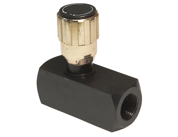
The Flow Control Valve from Buyers Products lets you speed up or slow down a function, such as plowing or dumping, for more precise and smooth control. The valve works by precisely controlling flow and shutoff in one direction, while automatically permitting full flow in the opposite direction. Choose from a range of NPT and SAE sizes in brass and steel.
Specifications
| Material | Carbon Steel |
|---|---|
| Maximum Body Pressure | 5000 |
| Maximum Flow Rate | 5 |
| Maximum Pressure | 5000 |
| Maximum Relief Pressure Setting | - |
| Number of Ports | 2 |
| Port Size | 1/4 NPTF |
The 1/4 Inch NPT Steel Flow Control Valve from Buyers Products represents a critical component in advanced hydraulic systems, engineered for the precise management of fluid dynamics within a diverse range of industrial, mobile, and agricultural applications. This highly robust and technically sophisticated valve is designed to offer unparalleled control over hydraulic actuator speed, ensuring operational efficiency, enhanced safety, and extended system longevity. Its core functionality lies in its ability to restrict fluid flow in one direction while allowing unimpeded flow in the opposite direction, a characteristic that makes it indispensable for applications requiring controlled motion in one phase of a cycle and rapid retraction or return in another.
Technical Overview and Operational Principles
At its heart, this flow control valve operates on the principle of variable orifice restriction coupled with an integrated check valve mechanism. In a hydraulic circuit, the valve is typically installed in series with a hydraulic cylinder or motor. When hydraulic fluid flows in the controlled direction, it passes through an adjustable orifice within the valve. By manipulating this orifice, the user can precisely regulate the volume of fluid permitted to pass per unit of time, thereby directly governing the speed of the connected actuator. For instance, to slow down a plow lift or a dump bed's descent, the orifice is constricted, reducing the flow rate and consequently the actuator's speed. Conversely, opening the orifice increases the flow rate and actuator speed.
The critical advantage of this valve's design is its unidirectional control coupled with a free-flow return. Integrated within the valve body is a check valve, which is essentially a one-way valve. When fluid attempts to flow in the uncontrolled direction (e.g., retracting a cylinder or returning a motor to its starting position), the check valve automatically opens, bypassing the restrictive orifice. This allows for full, unrestricted flow, ensuring that the return stroke or opposite motion occurs quickly and efficiently without unnecessary back pressure or energy loss. This dual functionality — precise control in one direction and rapid free flow in the other — significantly simplifies hydraulic circuit design and optimizes performance for many common applications.
The operational environment for such a valve is demanding. Hydraulic systems inherently involve high pressures and continuous fluid movement, which necessitates components built to exacting standards. The valve effectively manages hydraulic energy, converting potential energy (pressure) into kinetic energy (flow) in a controlled manner. Without precise flow control, hydraulic systems can exhibit erratic movements, leading to reduced productivity, increased wear on mechanical components, and potential safety hazards. This valve mitigates these risks by providing a stable and repeatable control mechanism.
Material Selection: Carbon Steel for Enduring Performance
The choice of Carbon Steel for the valve's construction is a deliberate engineering decision rooted in the material's superior mechanical properties and cost-effectiveness for high-pressure hydraulic applications. Carbon steel, primarily an alloy of iron and carbon (with carbon content up to 2.1% by weight), offers an exceptional balance of strength, hardness, ductility, and machinability. Specifically, the type of carbon steel used in high-pressure hydraulic components is typically a medium to high carbon variant, often heat-treated to enhance its tensile strength and yield strength.
Strength and Durability: With a Maximum Body Pressure and Maximum Pressure rating of 5000 PSI, the carbon steel body is engineered to withstand extreme internal hydraulic forces without deformation or failure. This high-pressure rating ensures the valve's integrity in demanding operational environments where sudden pressure spikes or continuous high-pressure cycles are common. The inherent toughness of carbon steel also provides excellent resistance to fatigue, a critical factor for components subjected to repetitive pressure loading over their operational lifespan. This robustness translates directly into a longer service life and reduced maintenance requirements for the end-user.
Wear Resistance: Components within a hydraulic valve, particularly the internal elements that interact with the fluid flow and the adjustment mechanisms, are subject to abrasive wear from fluid contaminants and erosive wear from high-velocity fluid. Carbon steel, especially when properly surface-finished or hardened, exhibits good wear resistance, contributing to the valve's sustained performance and accuracy over time. While carbon steel can be susceptible to corrosion in certain environments, its use in closed hydraulic systems where the fluid is typically oil-based and maintained with appropriate filtration largely mitigates this concern. For external exposure, protective coatings are often applied to further enhance corrosion resistance.
Manufacturing and Cost Efficiency: Carbon steel is a widely available and relatively economical material, making it a practical choice for mass-produced hydraulic components without compromising performance. Its excellent machinability allows for the precise fabrication of intricate valve geometries, ensuring tight tolerances and consistent performance characteristics from one unit to another. The ability to weld carbon steel also facilitates various manufacturing processes and potential repair scenarios, although internal valve components are typically replaced rather than repaired.
In contrast to brass, another common material for flow control valves, carbon steel offers significantly higher pressure ratings and superior resistance to mechanical stress, making it the preferred choice for heavy-duty industrial and mobile hydraulic systems where operational integrity under extreme conditions is paramount.
Pressure Ratings: 5000 PSI Maximum Body and Operating Pressure
The specification of a 5000 PSI (Pounds per Square Inch) Maximum Body Pressure and Maximum Pressure is a definitive indicator of this valve's suitability for high-performance hydraulic applications. This rating is not merely a theoretical limit but a meticulously determined value based on extensive material testing, structural analysis, and safety factor considerations.
Maximum Body Pressure: This refers to the highest static pressure that the valve body can safely withstand without yielding, fracturing, or leaking. It is a testament to the structural integrity of the carbon steel housing. In practical terms, it means the valve's physical structure can contain hydraulic fluid at this immense pressure, even under non-flow conditions or system standby. This rating provides a critical safety margin, ensuring that unexpected pressure spikes within the hydraulic circuit do not compromise the valve's containment capabilities, preventing catastrophic failures and fluid leaks.
Maximum Pressure (Operating Pressure): This refers to the highest pressure at which the valve is designed to operate continuously while maintaining its specified performance characteristics (e.g., flow control accuracy, sealing integrity, check valve function). Operating a valve consistently at or below its maximum pressure rating is crucial for ensuring its longevity and reliability. Exceeding this pressure, even momentarily, can lead to accelerated wear, internal damage to seals or moving parts, and potentially permanent deformation of the valve body, compromising its ability to function correctly and safely. A 5000 PSI operating pressure positions this valve for deployment in heavy machinery, construction equipment, large agricultural implements, and robust industrial hydraulic presses where high forces and pressures are the norm.
The implications of such a high-pressure rating are significant for system designers. It allows for the use of smaller bore cylinders to generate substantial forces, leading to more compact and efficient designs. Furthermore, it ensures compatibility with modern hydraulic power units and pumps that are increasingly capable of generating high pressures to meet the demands of powerful hydraulic actuators. When integrating this valve into a hydraulic system, it is imperative that all other components in the circuit—hoses, fittings, cylinders, pumps—are rated for at least the same or a higher maximum operating pressure to maintain overall system integrity and safety.
Maximum Flow Rate: 5 GPM for Controlled Actuation
The Maximum Flow Rate of 5 GPM (Gallons Per Minute) for this 1/4 Inch NPT valve signifies its optimal performance envelope within a hydraulic circuit. While a smaller flow rate compared to larger bore valves, 5 GPM is perfectly suited for precise speed control of actuators in applications where intricate movement and fine adjustment are prioritized over sheer velocity.
Sizing and Application Fit: For a 1/4-inch port size, 5 GPM represents a moderate to high flow capacity, indicative of applications involving smaller to medium-sized hydraulic cylinders or motors. Examples include precise angling of plow blades, controlled descent of small lifting platforms, delicate articulation of robotic arms, or the precise feeding mechanisms in manufacturing equipment. In these scenarios, uncontrolled rapid movement can lead to damage, inaccuracies, or safety hazards. The 5 GPM rating, when regulated by the valve's adjustable orifice, enables the operator to achieve smooth, predictable, and repeatable motion profiles.
Flow Control Mechanism: The valve's ability to precisely control flow within this 5 GPM range is crucial. By adjusting the orifice, the effective flow can be varied from a minimal trickle up to the full 5 GPM. This variability allows for dynamic control, adapting to different operational requirements or materials being processed. For instance, a function requiring slow, powerful engagement might operate at 1-2 GPM, while a faster return stroke would utilize the free flow capacity and maximum effective GPM of the actuator itself.
Considerations for System Design: When designing a hydraulic system around this valve, several factors related to flow rate must be considered:
- Pressure Drop: Any restriction in a hydraulic line, including a flow control valve, will induce a pressure drop. While the valve is designed to minimize this in the free-flow direction, controlled restriction inherently creates a pressure differential. System designers must account for this pressure drop to ensure sufficient pressure remains available at the actuator to perform the required work.
- Heat Generation: Restricting fluid flow generates heat. The energy lost due to friction as fluid passes through the constricted orifice is converted into thermal energy, which can raise the temperature of the hydraulic fluid. For a 5 GPM system, this effect is typically manageable, but in continuous duty cycles, proper hydraulic fluid cooling mechanisms should be in place to prevent fluid degradation and system inefficiency.
- Actuator Sizing: The maximum flow rate directly influences the maximum speed of a hydraulic cylinder or motor. For a cylinder, speed is calculated by (Flow Rate / Piston Area). For a motor, speed relates to (Flow Rate / Displacement per Revolution). Therefore, careful selection of actuator size in conjunction with the valve's flow rate ensures the desired operational speeds are achieved.
The 5 GPM rating, combined with the valve's high-pressure capability, signifies a robust solution for applications demanding both precision and power within its specified flow envelope.
Port Configuration: 2 Ports with 1/4 NPTF Threading
The design of this flow control valve features 2 ports with 1/4 NPTF threading, a standard and highly effective configuration for hydraulic fluid connections. This specific porting arrangement and threading type are crucial for understanding the valve's integration into a hydraulic circuit.
2-Port Design: A 2-port valve is inherently designed for in-line installation. It acts as a single flow path component, with one port serving as the inlet and the other as the outlet. In the context of this unidirectional flow control valve, one port will be designated for the controlled flow direction, and the other for the free-flow return. This simple, straightforward design makes installation and plumbing relatively easy, typically placing the valve directly in the line leading to or from the actuator whose speed is to be controlled.
1/4 NPTF Threading: NPTF stands for National Pipe Taper Fuel. This type of threading is a variant of the standard NPT (National Pipe Taper) thread, specifically designed to create a dry, mechanical seal without the need for additional sealants. The "F" in NPTF signifies "Fuel" or "Dryseal," indicating its capability to create an interference fit between the crests and roots of the mating threads, along with truncation of the threads, resulting in a metal-to-metal seal.
- Tapered Design: Both male and female NPTF threads are tapered. As the male fitting is tightened into the female port, the flanks, crests, and roots of the threads deform slightly and wedge together, forming a leak-proof seal.
- Dryseal Advantage: The primary benefit of NPTF over standard NPT is its ability to create a reliable seal without the use of thread sealants (like PTFE tape or pipe dope). This is particularly advantageous in hydraulic systems where contamination from sealant particles can be detrimental to sensitive components like pumps, valves, and cylinders. Eliminating sealants reduces assembly time, simplifies maintenance, and minimizes the risk of system contamination.
- Commonality: 1/4 NPTF is a widely recognized and utilized standard for hydraulic connections, ensuring broad compatibility with a vast array of hydraulic hoses, fittings, and components available in the market. This simplifies sourcing and replacement, making it a versatile choice for many applications.
When installing fittings into the 1/4 NPTF ports, it is crucial to use mating NPTF fittings to fully realize the dryseal benefit. While standard NPT fittings can sometimes be used with NPTF ports (and vice-versa), they typically require a thread sealant to achieve a leak-free connection, as the thread forms are slightly different and may not create the same interference fit.
Applications and Operational Benefits
The 1/4 Inch NPT Steel Flow Control Valve excels in a multitude of hydraulic applications where precise, single-direction speed control is paramount:
- Mobile Equipment: Essential for controlling functions on utility vehicles, construction equipment, and agricultural machinery. Examples include fine-tuning the speed of snow plow angling or lifting/lowering, managing the descent rate of dump bodies, controlling boom articulation on small cranes, or adjusting the speed of conveyor belts on mobile processing units. The robust steel construction ensures resilience in harsh outdoor environments.
- Material Handling: In fork-lift trucks, scissor lifts, and various conveyor systems, this valve ensures smooth and controlled lifting, lowering, or traversing motions. This prevents abrupt movements that could damage loads or endanger personnel.
- Industrial Automation: Critical for controlling the speed of hydraulic clamps, presses, and positioning mechanisms in manufacturing and assembly lines. Precise speed control reduces shock loads, improves product quality, and extends the life of machinery.
- Agricultural Machinery: Used for functions like adjusting the depth of tillage implements, controlling the speed of fertilizer spreaders, or managing the articulation of various attachments, enhancing precision farming operations.
The operational benefits derived from implementing this valve are extensive:
- Enhanced Precision and Control: The ability to precisely adjust actuator speed leads to finer control over the entire hydraulic operation. This is invaluable in tasks requiring delicate maneuvering or accurate positioning, significantly improving efficiency and output quality.
- Improved Safety: Uncontrolled or excessively fast movements in hydraulic systems pose significant safety risks. By governing the speed of operations, the valve mitigates the potential for accidents, spills, or equipment damage, creating a safer working environment.
- Reduced Wear and Tear: Smooth acceleration and deceleration of hydraulic actuators reduce shock loading and vibration throughout the system. This minimizes stress on cylinders, motors, pumps, hoses, and other components, contributing to their extended operational life and reducing maintenance costs.
- Optimized Cycle Times: While providing control, the free-flow return ensures that non-critical parts of a cycle (e.g., retraction of a cylinder) occur rapidly, optimizing overall cycle times and boosting productivity.
- Durability and Reliability: Constructed from carbon steel with high-pressure ratings, the valve is built to withstand rigorous use, offering reliable performance even in the most demanding hydraulic environments. Its robust design minimizes downtime and ensures consistent operation.
Installation and System Integration Considerations
Proper installation and thoughtful integration are crucial for maximizing the performance and longevity of the 1/4 Inch NPT Steel Flow Control Valve.
- Location in Circuit: The valve should be installed in the hydraulic line directly serving the actuator whose speed is to be controlled. To control cylinder extension, it would be placed in the line feeding the cap end. To control retraction, it would be in the line feeding the rod end. For motors, it controls speed in one direction of rotation.
- Flow Direction: Pay close attention to the flow direction indicators (usually an arrow) on the valve body. Ensure the controlled flow direction aligns with the desired phase of the actuator's movement, and the free-flow direction allows for rapid return. Incorrect installation will result in either no control or control in the wrong direction.
- Filtration: Hydraulic systems must employ adequate filtration upstream of the valve to prevent contaminants from entering the precision orifice or interfering with the check valve mechanism. Particles can cause blockages, accelerated wear, or erratic performance.
- System Pressure Compatibility: As previously mentioned, all components in the hydraulic circuit must be rated for at least 5000 PSI to match the valve's capability and ensure overall system integrity.
- Tubing and Fittings: Use appropriate 1/4 NPTF fittings and hydraulic tubing/hoses that are also rated for the system's maximum operating pressure and flow. Ensure all connections are tight and leak-free, adhering to proper torque specifications for NPTF connections to achieve the dryseal.
- Adjustment: The valve will typically feature an external adjustment screw or knob to regulate the orifice size. Initial system commissioning will involve adjusting this mechanism to achieve the desired actuator speed under typical load conditions. It's often beneficial to perform these adjustments with a pressure gauge to monitor system pressures.
This valve is a non-pressure-compensated flow control valve. This means that the controlled flow rate can vary slightly with changes in the load pressure acting on the actuator. While suitable for many applications, for highly critical tasks where load variations are significant and absolute constant speed is required regardless of load, a pressure-compensated flow control valve might be considered. However, for a vast array of mobile and industrial applications, the robust simplicity and cost-effectiveness of this non-compensated steel valve are highly advantageous.
Conclusion
The 1/4 Inch NPT Steel Flow Control Valve from Buyers Products stands as a testament to engineering excellence in hydraulic component design. Its construction from high-grade carbon steel, combined with a formidable 5000 PSI pressure rating and a precisely engineered 5 GPM flow capacity, ensures its readiness for the most demanding hydraulic applications. By offering precise, unidirectional speed control and rapid free flow in the opposite direction, this valve delivers tangible benefits in terms of operational precision, enhanced safety, and extended system longevity. The adherence to 1/4 NPTF threading further underscores its design for reliability and ease of integration into existing or new hydraulic systems, minimizing potential contamination and simplifying installation. For engineers and operators seeking a durable, high-performance solution to manage hydraulic actuator speeds with accuracy and control, this steel flow control valve is an indispensable choice, providing robust functionality that contributes directly to the efficiency and safety of diverse hydraulic machinery.