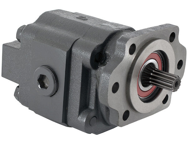
The H50 Series Hydraulic Gear Pump with Spline Shaft from Buyers Products is a sturdy, heavy duty bi-rotational pump that can be 2- or 4-bolt mounted in an SAE B mount. Choose from a range of models to meet your needs. All models feature a 7/8 in. by 13 spline shaft.
Specifications
| Direct Mount/Remote Mount | 2/4 Bolt SAE B |
|---|---|
| Direct or Remote Mount | Direct Mount |
| Displacement | 5 |
| Flow | 20 |
| Flow at 1000 RPM | 20 |
| Flow at 1200 RPM | 24 |
| Flow at 1500 RPM | 30 |
| Flow at 1800 RPM | 36 |
| Flow at 2100 RPM | 42 |
| Flow at 600 RPM | 12 |
| Flow at 900 RPM | 18 |
| Gear Size | 2.00 |
| Gear Width | 2.000 |
| Inlet Port Size | 1 1/4 NPT |
| Input Mount Type | Integral Bracket |
| Material | Cast Iron |
| Maximum Pressure | 2500 |
| Maximum Rotations Per Minute (RPM) | 2000 |
| Mount Type | SAE B 2/4 Bolt |
| Outlet Port Size | 1 1/4 NPT |
| Pilot Diameter | 4.00 |
| Ports (rear/side) | Rear/Side |
| Rear Port Size | 1 1/4 NPT |
| Rotation | Bi-Directional |
| Shaft Size | 7/8-13 |
| Shaft Type | Splined |
The H50 Series Hydraulic Gear Pump from Buyers Products, featuring a robust 7/8-13 Spline Shaft and a 2-inch diameter gear, represents a cornerstone in hydraulic power transmission for demanding mobile and industrial applications. This sophisticated component is engineered for unparalleled durability, consistent performance, and versatile integration, making it an optimal choice for systems requiring reliable fluid power generation under challenging operating conditions. As a heavy-duty, bi-rotational pump, it is designed to meet the rigorous demands of various hydraulic systems, offering flexibility through its 2- or 4-bolt SAE B mount options and a broad range of flow capabilities.
Technical Overview of Gear Pump Operation
At its core, the H50 Series operates on the fundamental principles of external gear pump technology. This design utilizes two identical, counter-rotating gears – a drive gear and an idler gear – housed within a precision-machined casing. As the drive shaft rotates, it engages the idler gear, causing both to rotate. Hydraulic fluid enters the inlet port, fills the spaces between the gear teeth and the pump casing, and is then carried around the periphery of the gears. Crucially, as the gear teeth mesh together at the outlet side, they create a positive displacement action, expelling the fluid under pressure into the hydraulic system. This continuous process ensures a smooth, non-pulsating flow of hydraulic fluid, vital for the precise control and efficient operation of hydraulic actuators.
The 2-inch diameter gear, as specified, and its corresponding 2.000-inch gear width are critical dimensions that directly influence the pump's volumetric displacement and, consequently, its flow rate. A larger gear diameter and width allow for greater fluid volume to be displaced per revolution, contributing to the pump's substantial 5 cubic inch displacement. This design choice underscores the H50 Series' suitability for applications requiring significant hydraulic power, translating rotational mechanical energy into hydraulic energy with high volumetric efficiency, even under high pressure loads. The precision manufacturing of these gears, often involving advanced machining and heat treatment processes, minimizes internal leakage (slip) and maximizes the effective delivery of fluid, ensuring that the pump maintains its performance characteristics over an extended operational lifespan.
Spline Shaft – The Backbone of Power Transmission
The integral 7/8-13 spline shaft is a definitive feature distinguishing the H50 Series for heavy-duty applications. A spline shaft employs a series of ridges or teeth (splines) machined along its circumference, designed to mate precisely with corresponding grooves in a coupling or power take-off (PTO) unit. The specification "7/8-13" denotes a nominal shaft diameter of 7/8 inches and 13 splines. This configuration provides a superior method of transmitting torque compared to traditional keyways, offering several distinct advantages:
- Enhanced Torque Capacity: Splines distribute the torque load over a larger surface area and multiple engagement points, significantly increasing the shaft's capacity to transmit high torque without localized stress concentrations. This minimizes the risk of shear failure, twisting, or wear, which can be common in keyed shafts under heavy loads.
- Improved Alignment and Reduced Wear: The multiple contact points of a spline connection facilitate better concentricity and angular alignment between the pump shaft and the driving mechanism. This reduces fretting wear, vibration, and noise, contributing to a longer service life for both the pump and the prime mover (e.g., engine PTO).
- Greater Strength and Durability: The material around the splines remains largely intact, preserving the shaft's strength. In contrast, a keyway slot removes a significant portion of the shaft's cross-section, creating a stress riser that can lead to premature failure. The 7/8-inch diameter indicates a substantial shaft, further enhancing its robust nature for demanding hydraulic systems.
- Secure Connection: Splined connections offer a positive, backlash-free engagement, ensuring efficient and reliable power transfer even during dynamic load changes and reversals, which is particularly beneficial for bi-directional pumps.
The specific 7/8-13 spline profile is a widely recognized standard in the industry, facilitating interchangeability and compatibility with a broad array of hydraulic components and drive systems. This standardization simplifies integration and reduces the complexity of sourcing replacement parts or adapting the pump to existing machinery.
Mounting Versatility: SAE B 2/4 Bolt and Pilot Diameter
The H50 Series pump offers exceptional mounting flexibility with its SAE B 2/4 bolt pattern. The Society of Automotive Engineers (SAE) B mount is a standard widely adopted in the mobile and industrial hydraulic industries, ensuring broad compatibility. The option of either a 2-bolt or 4-bolt configuration provides further adaptability:
- 2-Bolt Mounting: Often suitable for applications where space is at a premium or for pumps with moderate weight, offering a straightforward and robust connection.
- 4-Bolt Mounting: Provides increased stability and load distribution, which is particularly advantageous for heavier pumps, higher vibration environments, or applications where precise alignment needs to be maintained under extreme conditions.
The pump is designated as "Direct Mount," meaning it is typically connected directly to a prime mover, such as an engine's power take-off (PTO), or an auxiliary gearbox. This direct connection minimizes losses and simplifies the hydraulic system layout. The "Input Mount Type: Integral Bracket" further streamlines installation by providing a self-contained mounting solution.
A critical dimension for proper mounting is the 4.00-inch pilot diameter. The pilot diameter is a precision-machined concentric projection or recess on the pump's mounting flange that mates with a corresponding bore on the mating component (e.g., PTO adapter). Its purpose is to ensure precise concentric alignment of the pump shaft with the driving shaft. Correct piloting prevents misalignment, which can lead to excessive wear on the shaft, bearings, and seals, premature pump failure, and inefficient power transmission. The 4.00-inch pilot diameter adheres to common industry standards, ensuring a secure and accurate fit.
Bi-Directional Rotation – Expanding Application Horizons
The bi-directional rotation capability of the H50 Series is a significant advantage, dramatically enhancing its versatility across various hydraulic applications. Unlike uni-directional pumps that are restricted to rotating in one direction, a bi-rotational pump can operate efficiently regardless of the input shaft's rotational direction (clockwise or counter-clockwise). This feature eliminates the need for specific pump models tailored to clockwise or counter-clockwise drive systems, simplifying inventory management and installation. For complex hydraulic systems that may require reversing fluid flow or for equipment where the drive source's rotation is not fixed, a bi-directional pump is indispensable. It ensures that the pump can be universally applied without concern for the rotational compatibility of the prime mover.
Robust Construction: Cast Iron Material
The H50 Series pump is constructed from high-quality cast iron. This material choice is deliberate and offers several critical benefits for hydraulic pump applications:
- Exceptional Strength and Rigidity: Cast iron possesses high compressive strength and rigidity, making it ideal for housing components subjected to internal pressures up to 2500 PSI. This inherent strength minimizes housing deflection and internal leakage under load, maintaining consistent volumetric efficiency.
- Excellent Vibration Damping: Cast iron has superior vibration damping characteristics compared to other metals like steel or aluminum. This property helps to absorb and dissipate vibrations generated during pump operation, contributing to quieter running and reduced stress on surrounding components, thereby extending overall system life.
- Durability and Wear Resistance: The microstructure of cast iron provides good wear resistance, particularly important for components exposed to the abrasive nature of hydraulic fluid over time. This contributes to the pump's "heavy duty" designation and its long-term reliability in harsh environments.
- Thermal Stability: Cast iron maintains its mechanical properties across a wide range of operating temperatures, ensuring consistent performance in varying environmental conditions.
- Cost-Effectiveness: While offering premium performance, cast iron remains a cost-effective material for high-volume manufacturing, allowing for a robust product without prohibitive cost implications.
Performance Specifications: Displacement, Flow, and Pressure
The detailed specifications provided for the H50 Series highlight its formidable hydraulic capabilities:
-
Displacement: 5 Cubic Inches per Revolution (CIR)
Displacement is a fundamental parameter for any hydraulic pump, defining the volume of fluid displaced with each complete rotation of the pump shaft. A 5 CIR displacement signifies that for every full rotation of the drive shaft, the pump effectively moves 5 cubic inches of hydraulic fluid. This substantial displacement is indicative of a pump designed for systems requiring considerable fluid flow and power. -
Flow Rates: GPM at Various RPMs
The flow rate, typically measured in Gallons Per Minute (GPM), is directly proportional to the pump's displacement and rotational speed (RPM). The H50 Series demonstrates excellent flow characteristics across its operational speed range:- Flow at 600 RPM: 12 GPM
- Flow at 900 RPM: 18 GPM
- Flow at 1000 RPM: 20 GPM
- Flow at 1200 RPM: 24 GPM
- Flow at 1500 RPM: 30 GPM
- Flow at 1800 RPM: 36 GPM
- Flow at 2100 RPM: 42 GPM
-
Maximum Pressure: 2500 PSI
The maximum pressure rating of 2500 PSI (pounds per square inch) is a critical indicator of the pump's structural integrity and its ability to generate significant force within a hydraulic system. This pressure capability makes the H50 Series suitable for a wide array of heavy-duty applications that demand high force generation, such as lifting heavy loads, operating powerful cylinders, or driving high-torque hydraulic motors. Adhering to this maximum pressure rating is essential to ensure the longevity and safe operation of the pump and the entire hydraulic circuit. -
Maximum Rotations Per Minute (RPM): 2000 RPM
The specified maximum RPM of 2000 defines the upper operational speed limit for the pump. Operating within or below this limit ensures that internal components, such as bearings, gears, and seals, are not subjected to excessive centrifugal forces or frictional heat, thereby preserving the pump's intended service life and efficiency. While the flow rates are listed up to 2100 RPM, it's important to note that the *maximum continuous operating RPM* is 2000, indicating that brief excursions might be possible but continuous operation at higher speeds is not recommended for optimal longevity.
Porting and System Integration
The H50 Series features generous port sizing for optimal system integration:
- Inlet Port Size: 1 1/4 NPT
- Outlet Port Size: 1 1/4 NPT
- Rear Port Size: 1 1/4 NPT
- Ports (rear/side): Rear/Side
The 1 1/4 NPT (National Pipe Taper) port sizes are substantial, ensuring unrestricted flow of hydraulic fluid into and out of the pump. Appropriately sized inlet ports are crucial for preventing cavitation, a phenomenon caused by insufficient fluid supply to the pump, which can lead to erosion, noise, and pump damage. Similarly, large outlet ports minimize pressure drop and heat generation, optimizing overall system efficiency. The availability of both rear and side porting options offers considerable flexibility for plumbing configurations, allowing engineers to design more compact and efficient hydraulic layouts tailored to specific spatial constraints or system requirements.
Applications and Industries
Given its robust design and impressive performance specifications, the H50 Series Hydraulic Gear Pump is ideally suited for a diverse range of demanding applications across various industries:
- Refuse & Waste Management: Powering compaction mechanisms, lifters, and dump functions on refuse trucks.
- Construction Equipment: Operating loaders, excavators, dozers, and other heavy machinery requiring reliable hydraulic power for movement and articulation.
- Agricultural Machinery: Providing power for implements, steering, and lifting on tractors, harvesters, and sprayers.
- Commercial Vehicles: Actuating dump beds on dump trucks, operating cranes on utility trucks, and powering various auxiliary functions on municipal vehicles like snowplows and salt spreaders.
- Material Handling: Driving conveyors, lifts, and clamps in industrial settings.
- Forestry Equipment: Supplying hydraulic power for log splitters, chippers, and grapples.
- Industrial Power Units: Integral component in stationary hydraulic power units for factory automation, pressing, and clamping operations.
Its heavy-duty cast iron construction, high-pressure capability, bi-directional rotation, and robust spline shaft make it a reliable choice for environments where equipment faces continuous operation, heavy loads, and exposure to harsh elements.
Advantages and Benefits
The H50 Series Hydraulic Gear Pump delivers a compelling value proposition through a combination of key advantages:
- Exceptional Durability and Longevity: Constructed from high-strength cast iron with precision-engineered gears and shaft, ensuring extended operational life even in the most strenuous applications.
- Consistent and Reliable Performance: Offers predictable flow rates and stable pressure generation up to 2500 PSI, crucial for precise control and efficient operation of hydraulic systems.
- Versatile Application: Bi-directional rotation and flexible SAE B 2/4 bolt mounting options allow for broad compatibility and simplified integration into diverse hydraulic circuits.
- Efficient Power Transmission: The 7/8-13 spline shaft ensures maximum torque transfer from the prime mover to the pump, minimizing power loss and maximizing mechanical efficiency.
- Simplified Maintenance: Gear pumps are known for their relatively simple design, which translates to easier troubleshooting and lower maintenance requirements compared to more complex pump types.
- Reduced Downtime: The robust construction and reliable operation contribute to fewer breakdowns and less unscheduled maintenance, maximizing equipment uptime and productivity.
Installation and Maintenance Best Practices
To ensure optimal performance and longevity of the H50 Series pump, adherence to best practices in installation and maintenance is paramount:
- Proper Alignment: Critically important during direct mounting, the 4.00-inch pilot diameter must be accurately aligned with the drive mechanism to prevent excessive radial loads on the shaft and bearings. Misalignment is a leading cause of premature pump failure.
- Clean Hydraulic Fluid: Maintain strict fluid cleanliness standards using appropriate filtration. Contamination is the most common cause of wear and damage in hydraulic components, especially in precision-machined gear pumps.
- Correct Fluid Type: Use only hydraulic fluid recommended by the manufacturer, suitable for the operating temperature range and pressure requirements.
- Adequate Inlet Conditions: Ensure the suction line is correctly sized and free from obstructions to prevent cavitation. The inlet should always be flooded to prevent air ingestion.
- System Pressure Relief: Integrate appropriate pressure relief valves within the hydraulic circuit to protect the pump and system components from over-pressurization.
- Regular Inspections: Periodically check for leaks, unusual noise, vibrations, and excessive heat, which can indicate impending issues. Monitor fluid levels and quality.
By integrating the H50 Series Hydraulic Gear Pump, systems benefit from a foundation of reliable, high-performance fluid power. Its technical specifications, from the precisely engineered 2-inch gears and 7/8-13 spline shaft to its robust cast iron construction and adaptable mounting, collectively represent a commitment to durability and operational excellence in the most demanding hydraulic applications.