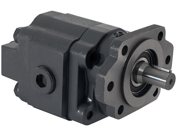
The H50 Series Hydraulic Gear Pump with Keyed Shaft from Buyers Products is a sturdy, heavy duty bi-rotational pump that can be 2-bolt or 4-bolt mounted in an SAE B mount. This pump handles greater flow rates up to 54 GPM for a 2-1/2 in. gear width. Choose from a range of models with flow rates and pressure ratings to meet your working needs. All of the models feature a 1 in. keyed shaft.
Specifications
| Direct Mount/Remote Mount | 2/4 Bolt SAE B |
|---|---|
| Direct or Remote Mount | Remote Mount |
| Displacement | 6 |
| Flow | 27 |
| Flow at 1000 RPM | 27 |
| Flow at 1200 RPM | 32.4 |
| Flow at 1500 RPM | 40.50 |
| Flow at 1800 RPM | 48.60 |
| Flow at 2100 RPM | 56.70 |
| Flow at 600 RPM | 16.20 |
| Flow at 900 RPM | 24.30 |
| Gear Size | 2.50 |
| Gear Width | 2.500 |
| Inlet Port Size | 1 1/4 NPT |
| Input Mount Type | Integral Bracket |
| Material | Cast Iron |
| Maximum Pressure | 2500 |
| Maximum Rotations Per Minute (RPM) | - |
| Mount Type | SAE B 2/4 Bolt |
| Outlet Port Size | 1 1/4 NPT |
| Pilot Diameter | 4.00 |
| Ports (rear/side) | Rear/Side |
| Rear Port Size | 1 1/2 NPT |
| Rotation | Bi-Directional |
| Shaft Size | 1 |
| Shaft Type | Round/Keyed |
| Side Port Size | 1 1/4 NPT |
The H50 Series Hydraulic Gear Pump from Buyers Products represents a pinnacle of engineering excellence in positive displacement pumping technology, specifically designed for robust performance in demanding hydraulic systems. This unit, characterized by its 1-inch keyed shaft and substantial 2-1/2 inch diameter gear, is meticulously crafted to deliver reliable and efficient power transmission across a broad spectrum of industrial and mobile applications. Its inherent bi-rotational capability, coupled with versatile SAE B 2-bolt or 4-bolt mounting options, positions it as an exceptionally adaptable component in complex hydraulic circuits.
Fundamental Principles of External Gear Pumps
An external gear pump, such as the H50 Series, operates on the principle of positive displacement. This means it delivers a fixed amount of fluid with each revolution of its gears, regardless of the system pressure, assuming adequate inlet conditions. The pump consists of two meshing gears – a drive gear and an idler gear – housed within a precisely machined casing. As the drive shaft rotates, powered by an external prime mover (e.g., an electric motor or internal combustion engine), it turns the drive gear. The intermeshing teeth create suction at the inlet port, drawing hydraulic fluid into the expanding pockets between the gear teeth and the pump housing. The rotating gears then transport this fluid around the periphery of the casing. As the gear teeth re-mesh at the outlet side, the fluid pockets are compressed, forcing the hydraulic fluid out through the discharge port under pressure. This continuous action generates a smooth, consistent flow of hydraulic power.
Robust Construction and Material Science: The Cast Iron Advantage
The H50 Series pump is constructed from high-grade cast iron, a material specifically chosen for its superior mechanical properties and suitability for hydraulic pump casings. Cast iron offers exceptional tensile strength, rigidity, and resistance to deformation under high operating pressures and temperatures. Its inherent damping characteristics help to reduce noise and vibration during operation, contributing to a smoother system performance and extended component life. Furthermore, cast iron exhibits excellent wear resistance, particularly when exposed to the abrasive elements sometimes present in hydraulic fluids, ensuring the pump's internal clearances are maintained over prolonged periods. This robust material choice underpins the "sturdy, heavy-duty" designation, guaranteeing durability and reliability in the most challenging operational environments.
Precision Gearing: 2-1/2 Inch Diameter for Optimal Displacement
Central to the H50 Series' performance is its precisely engineered 2-1/2 inch diameter gear set. The gear width, specified at 2.500 inches, directly influences the pump's volumetric displacement. In an external gear pump, the displacement refers to the volume of fluid transferred per revolution of the drive shaft, typically measured in cubic inches per revolution (CIR) or cubic centimeters per revolution (CCR). The specification of '6' for displacement likely corresponds to 6 CIR (cubic inches per revolution). A larger gear width and diameter allows for greater fluid displacement per revolution, translating into higher flow rates at a given rotational speed. The gears themselves are typically made from hardened alloy steel, machined to tight tolerances to minimize internal leakage and optimize volumetric efficiency. The precise meshing of these gears is critical for minimizing pulsation and ensuring consistent fluid delivery, which is essential for accurate control in hydraulic systems. The 2-1/2 inch gear width enables the pump to achieve substantial flow rates, reaching up to 54 GPM, accommodating the demands of various high-flow applications.
The Critical Role of the 1-Inch Keyed Shaft
The 1-inch keyed shaft is a fundamental mechanical interface for transmitting rotary power from the prime mover to the pump's internal gears. The "keyed" design signifies a positive mechanical interlock between the shaft and the coupling mechanism, preventing slippage and ensuring direct torque transfer. A key, a small rectangular metal piece, fits into a corresponding keyway machined into both the shaft and the mating component (e.g., a PTO or electric motor coupling), creating a robust, non-slip connection. The 1-inch diameter provides ample cross-sectional area to withstand high torsional stresses associated with transmitting significant power required for robust hydraulic operations. The shaft itself is typically crafted from high-strength, heat-treated alloy steel, ensuring its resistance to fatigue, bending, and shear forces under continuous, heavy-duty operation. Proper alignment of the shaft with the prime mover is paramount during installation to prevent excessive bearing loads and premature wear.
Mounting Flexibility: SAE B 2-Bolt or 4-Bolt and Pilot Diameter
The H50 Series offers exceptional versatility through its adherence to the SAE B mounting standard, accommodating both 2-bolt and 4-bolt configurations. SAE (Society of Automotive Engineers) mounting standards are critical for interchangeability and compatibility across various hydraulic components and power take-offs (PTOs). The SAE B standard specifies a particular bolt circle diameter and pilot diameter, ensuring secure and precise alignment between the pump and its power source. The specified 4.00-inch pilot diameter, also known as the register diameter, serves as a crucial guide for concentricity, ensuring the pump shaft is perfectly aligned with the drive shaft of the prime mover. This precise alignment minimizes vibration, reduces stress on bearings and seals, and significantly extends the operational life of the pump and the entire hydraulic system. The ability to choose between 2-bolt and 4-bolt patterns further enhances mounting flexibility, allowing integration into diverse existing or new equipment designs, whether for direct or remote mount applications.
Bi-Directional Rotation for Enhanced System Versatility
A significant feature of the H50 Series is its bi-rotational capability. Unlike uni-directional pumps that are restricted to rotating in one direction (either clockwise or counter-clockwise), bi-directional pumps can operate efficiently regardless of the input shaft's rotational direction. This versatility is achieved through internal design elements, often involving symmetrical porting and pressure-balanced wear plates, which allow the pump to maintain its performance characteristics whether the shaft is turning clockwise or counter-clockwise. This feature simplifies inventory management, as a single pump model can serve applications that might otherwise require two distinct uni-directional pumps. More importantly, it offers greater design flexibility for hydraulic systems where the prime mover's rotation might vary or where the same pump needs to perform different functions requiring reverse flow, such as operating a reversible hydraulic motor or an actuator in both extending and retracting cycles.
Flow Rate Dynamics: Up to 56.70 GPM for Demanding Applications
The H50 Series provides a comprehensive range of flow rates, with capabilities extending up to 56.70 GPM (gallons per minute) at 2100 RPM, and maintaining robust flow across various rotational speeds. Hydraulic flow rate is a direct function of the pump's displacement and its rotational speed. The provided specifications illustrate this relationship clearly:
- Flow at 600 RPM: 16.20 GPM
- Flow at 900 RPM: 24.30 GPM
- Flow at 1000 RPM: 27 GPM
- Flow at 1200 RPM: 32.4 GPM
- Flow at 1500 RPM: 40.50 GPM
- Flow at 1800 RPM: 48.60 GPM
- Flow at 2100 RPM: 56.70 GPM
These figures demonstrate a linear increase in flow with increasing RPM, which is characteristic of positive displacement pumps. This precise control over flow allows system designers to accurately match pump output to the specific speed requirements of hydraulic cylinders, motors, and other actuators. The capacity to deliver substantial flow rates like 56.70 GPM makes the H50 Series suitable for large-scale operations requiring rapid movement of heavy loads or high-speed machinery functions, ensuring efficient cycle times and enhanced productivity.
Pressure Handling: A Maximum of 2500 PSI
The maximum pressure rating of 2500 PSI (pounds per square inch) is a critical parameter for any hydraulic pump, defining the maximum continuous operating pressure it can safely withstand without compromising structural integrity or performance. This robust pressure capability allows the H50 Series pump to generate the force necessary to actuate heavy-duty hydraulic cylinders and motors in demanding applications. The pump's ability to maintain high pressure is directly related to the strength of its casing, the precision of its internal components, and the effectiveness of its sealing mechanisms. Operating a pump above its rated maximum pressure can lead to premature wear, seal failure, structural damage, and system inefficiency. The 2500 PSI rating indicates a pump designed for substantial workload, capable of driving powerful hydraulic functions required in construction, agriculture, and municipal service vehicles.
Versatile Porting Options: Inlet and Outlet Configuration
The H50 Series offers comprehensive porting flexibility with specified inlet and outlet port sizes, including rear and side port options. The primary inlet and outlet ports are 1 1/4 NPT (National Pipe Taper), while a larger 1 1/2 NPT rear port is also available. NPT threads are a widely used standard in North America for hydraulic connections, providing a robust, leak-resistant seal through their tapered design. Proper sizing of inlet ports is crucial to prevent cavitation, a phenomenon where insufficient fluid supply to the pump inlet causes vapor bubbles to form and collapse, leading to noise, vibration, and severe damage to pump components. The generous 1 1/4 NPT and 1 1/2 NPT port sizes help ensure an unrestricted flow of hydraulic fluid to the pump, minimizing pressure drop and mitigating the risk of cavitation. The availability of both rear and side porting options provides significant installation flexibility, allowing hydraulic lines to be routed optimally within the confines of various equipment designs, improving aesthetics, and simplifying maintenance access.
Understanding Displacement: The Heart of Flow Generation
The displacement of '6' listed in the specifications refers to the pump's volumetric capacity per revolution, typically expressed as 6 cubic inches per revolution (CIR). This metric is fundamental to understanding a pump's theoretical flow output. For an external gear pump, displacement is primarily determined by the dimensions of the gears – specifically, their diameter, width, and tooth profile. A pump with a displacement of 6 CIR will theoretically move 6 cubic inches of fluid for every full rotation of its drive shaft. This direct relationship allows for predictable flow rates based on the input RPM, which is critical for precise system design and control. The consistency of displacement across varying operating conditions is a hallmark of positive displacement pumps, distinguishing them from non-positive displacement pumps (e.g., centrifugal pumps) whose flow output is highly dependent on system pressure.
Hydraulic System Efficiencies: Volumetric, Mechanical, and Overall
While gear pumps are known for their robustness, their operational efficiency is a composite of several factors:
- Volumetric Efficiency: This measures the ratio of actual fluid output to theoretical fluid output. It is primarily affected by internal leakage (slip) across the gear tips, sides, and through the clearance between the gear faces and the wear plates. High-precision manufacturing, tight tolerances, and effective pressure-balanced designs (common in modern gear pumps) are crucial for maximizing volumetric efficiency, especially at higher pressures.
- Mechanical Efficiency: This relates to the power lost due to friction within the pump, including bearing friction, gear tooth friction, and viscous drag of the fluid itself. High-quality bearings, advanced gear tooth profiles, and optimized material surfaces contribute to higher mechanical efficiency.
- Overall Efficiency: This is the product of volumetric and mechanical efficiencies. It represents the ratio of hydraulic power output to mechanical power input. A high overall efficiency indicates that more of the input power is converted into useful hydraulic work, resulting in lower energy consumption and reduced heat generation. The H50 Series is engineered to achieve high overall efficiency, contributing to energy savings and cooler system operation.
Applications of the H50 Series Hydraulic Gear Pump
Given its robust design, versatile mounting, bi-directional capability, and significant flow and pressure ratings, the H50 Series Hydraulic Gear Pump is ideally suited for a wide array of heavy-duty applications:
- Mobile Hydraulics: Commonly found on municipal vehicles such as snowplows, dump trucks, refuse compactors, and salt spreaders, where reliable hydraulic power is essential for operating attachments and utility functions.
- Construction Equipment: Essential for powering auxiliary functions on excavators, loaders, backhoes, and other heavy machinery, driving attachments like augers, hammers, and grapples.
- Agricultural Machinery: Used in tractors, harvesters, and irrigation systems to power implements, steering, and various hydraulic functions vital for modern farming operations.
- Material Handling: Integral to forklifts, telescopic handlers, and other lifting equipment for hoist, tilt, and steering functions.
- Industrial Power Units: Can be incorporated into stationary hydraulic power units (HPUs) for various manufacturing processes, presses, and automation systems requiring a consistent and reliable hydraulic power source.
Its ability to handle greater flow rates up to 54 GPM for a 2-1/2 inch gear width, combined with a 2500 PSI maximum pressure, ensures it can meet the rigorous demands of these diverse industries, providing consistent performance even in harsh operating conditions.
Maintenance and Longevity Considerations
To maximize the operational life and maintain the peak performance of the H50 Series Hydraulic Gear Pump, several maintenance considerations are crucial:
- Fluid Cleanliness: Hydraulic fluid contamination is the leading cause of pump failure. Regular filtration and monitoring of fluid cleanliness levels are paramount. Recommended ISO cleanliness codes should always be adhered to.
- Fluid Type and Viscosity: Using the correct type and viscosity of hydraulic fluid, as recommended by the manufacturer, is essential for proper lubrication, heat dissipation, and sealing. Operating with incorrect fluid or viscosity can lead to cavitation, increased wear, and reduced efficiency.
- Temperature Management: Maintaining the hydraulic fluid within its optimal operating temperature range is vital. Excessive temperatures accelerate fluid degradation and can damage seals, while excessively low temperatures can increase fluid viscosity, leading to poor pump performance and cavitation.
- Inlet Conditions: Ensure that the pump's inlet line is correctly sized, free of restrictions, and submerged below the fluid level in the reservoir to prevent cavitation. Inspect suction filters regularly.
- Shaft Alignment: Proper alignment between the pump shaft and the prime mover's shaft is critical. Misalignment causes excessive bearing loads, vibration, and premature wear of the shaft, bearings, and coupling.
- Regular Inspections: Periodically inspect for external leaks, unusual noises, and excessive vibration, which can be indicators of impending issues.
Conclusion: An Engineering Solution for Demanding Hydraulics
The H50 Series Hydraulic Gear Pump with its 1-inch keyed shaft and 2-1/2 inch diameter gear from Buyers Products stands as a testament to robust hydraulic engineering. From its heavy-duty cast iron construction to its precise gear machining and bi-rotational capability, every aspect of its design is optimized for durability, efficiency, and versatility. With flow rates reaching up to 56.70 GPM and a maximum pressure rating of 2500 PSI, this pump is capable of handling the most demanding tasks in mobile and industrial hydraulic systems. Its adherence to SAE B mounting standards and flexible porting options ensure seamless integration into a wide range of applications. For professionals seeking a reliable, high-performance hydraulic power source that can withstand rigorous operational cycles and deliver consistent power, the H50 Series offers an exceptional and enduring solution, embodying a commitment to quality and longevity in the challenging world of fluid power.