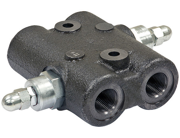
The Cross-Over Relief Valve (NPTF Port) from Buyers Products protects your plow and other system components from damage whenever a circuit is overloaded. It provides relief to angling cylinders in situations when a plow may encounter obstructions. It is designed to fit NPTF ports and is available in two models to meet your needs.
Specifications
| Material | Cast Iron |
|---|---|
| Maximum Flow Rate | 20 |
| Maximum Pressure | 3000 |
| Maximum Relief Pressure Setting | 1500 |
| Number of Ports | 4 |
| Port Size | 3/4 NPTF |
The 3/4 Inch NPTF Cross-Over Relief Valve with a 20 GPM capacity represents a critical component in the safeguarding and optimization of hydraulic systems, particularly those operating in demanding conditions such as snow removal, construction, and agricultural applications. Engineered for robust performance and superior protection, this valve is indispensable for maintaining the integrity and prolonging the operational life of hydraulic actuators and associated plumbing. Its specific design and technical specifications underscore its suitability for high-stress environments where sudden impacts or overloads are common occurrences.
Fundamentals of Cross-Over Relief Valve Technology
A cross-over relief valve, also known as a dual-pilot relief valve or a cylinder relief valve, is a sophisticated hydraulic safety device designed to protect double-acting hydraulic cylinders from excessive pressure differentials. Unlike standard single-line relief valves, which typically protect a pump or a single circuit line, a cross-over relief valve is specifically configured to span both work ports (A and B) of a double-acting cylinder. This unique architecture allows it to sense and alleviate pressure spikes originating from either side of the cylinder, providing comprehensive bi-directional protection.
The operational principle involves two independent relief valve cartridges, each set to a specific pressure threshold, working in tandem within a single housing. When the pressure in port A (e.g., extending the cylinder) exceeds the set relief pressure, the corresponding relief valve opens, diverting excess fluid from port A to port B, or vice-versa. This fluid transfer mechanism prevents hydraulic lock-up or structural damage to the cylinder, hoses, or mounting points by dissipating the energy of the pressure spike. In practical terms, this means that if a snow plow blade, actuated by a double-acting cylinder, strikes an immovable object, the resultant shock load would generate a sudden, localized pressure increase in the cylinder. Without a cross-over relief valve, this pressure could rupture seals, bend the cylinder rod, or even damage the plow structure. This 3/4 Inch NPTF Cross-Over Relief Valve, with its 1500 PSI maximum relief pressure setting, is precisely calibrated to address such scenarios, ensuring the controlled release of pressure and safeguarding the entire assembly.
Detailed Technical Specifications and Their Implications
Port Size: 3/4 Inch NPTF
The designation "3/4 Inch NPTF" refers to the National Pipe Taper Fuel and Oil port standard. This is a crucial specification for ensuring proper integration and leak-free performance within a hydraulic system. NPTF threads are designed to create a mechanical seal without the need for additional sealants, though thread sealant is often recommended for added security and ease of assembly. The tapered design of the threads (1:16 taper) ensures that as the male and female threads are tightened, they wedge together, forming a metal-to-metal seal. The "F" in NPTF signifies "Fuel and Oil," indicating that these threads are specifically manufactured to tighter tolerances than standard NPT (National Pipe Taper) threads, making them ideal for high-pressure fluid transfer where zero leakage is paramount. A 3/4 inch port size indicates the nominal internal diameter of the connection, suitable for hydraulic circuits requiring moderate to high flow rates, consistent with the 20 GPM maximum flow rate of this specific valve. Using correctly matched NPTF fittings is essential for preventing leaks, maintaining system pressure, and avoiding potential environmental contamination from hydraulic fluid.
Maximum Flow Rate: 20 GPM (Gallons Per Minute)
A maximum flow rate of 20 GPM signifies the optimal volume of hydraulic fluid that can pass through the valve without incurring excessive pressure drop or generating undue heat. This specification is critical for proper system sizing. In applications like snow plows, which involve rapidly extending and retracting cylinders for angling or lifting, the hydraulic pump must deliver a sufficient flow rate to achieve desired operational speeds. If the valve's flow rate capacity is lower than the system's requirements, it can restrict fluid movement, leading to sluggish cylinder response, increased system pressure, and premature wear of hydraulic components due to heat generation. Conversely, a valve with a significantly higher flow rate capacity than needed might be oversized, leading to unnecessary cost. The 20 GPM rating makes this valve suitable for a wide range of medium-duty mobile hydraulic equipment, ensuring that cylinders can operate efficiently and responsively while maintaining adequate protection against pressure surges.
Maximum Pressure: 3000 PSI
The maximum system pressure rating of 3000 PSI (Pounds Per Square Inch) defines the highest continuous operating pressure the valve body and internal components can safely withstand without structural failure or deformation. This is a fundamental safety and durability parameter. Hydraulic systems, by their nature, often operate at very high pressures to generate significant force from compact components. A rating of 3000 PSI places this cross-over relief valve firmly within the realm of high-performance hydraulic components, suitable for demanding industrial and mobile applications. It ensures that the valve itself will not be the weakest link in a system designed to operate at or below this pressure. Selecting a valve with an insufficient maximum pressure rating for a given application can lead to catastrophic failure, posing significant safety hazards and expensive equipment damage.
Maximum Relief Pressure Setting: 1500 PSI
The maximum relief pressure setting of 1500 PSI is the adjustable upper limit at which the internal relief cartridges can be set to open. While the valve itself can withstand up to 3000 PSI, the operational intent of the relief function is to intervene at a lower, specified pressure to protect the cylinder and circuit components. This 1500 PSI setting is particularly relevant for the typical operating pressures of many plow angling cylinders and similar actuators. The ability to set this pressure is crucial because different cylinders and applications have varying mechanical strength limits. Setting the relief pressure too high could allow damaging forces to act on the cylinder before the valve activates; setting it too low might cause the valve to activate unnecessarily, leading to inefficient operation or unwanted cylinder movement. This adjustability provides the flexibility to fine-tune the system's protective threshold to match the specific requirements and structural limits of the attached hydraulic actuator, offering a precise balance between performance and protection.
Material: Cast Iron
The choice of cast iron for the valve body is a deliberate engineering decision based on a balance of strength, durability, cost-effectiveness, and manufacturing feasibility. Cast iron, specifically grey cast iron, offers excellent compressive strength, good damping characteristics to absorb vibrations, and is relatively resistant to wear and deformation under typical hydraulic operating conditions. Its inherent properties make it suitable for manufacturing complex shapes, such as valve bodies with intricate internal passages, through casting processes. Cast iron also provides good resistance to corrosion in environments where hydraulic fluid is present, especially when appropriate surface treatments are applied. For heavy-duty applications like snow plowing, where components are exposed to harsh weather, road salts, and potential physical impacts, the robustness of cast iron ensures the valve's longevity and reliable performance. While other materials like ductile iron or steel alloys might offer superior tensile strength or impact resistance, cast iron provides an optimal combination of properties for the specified application and pressure ratings, contributing to the overall reliability and economic viability of the product.
Number of Ports: 4
The presence of four ports is characteristic of a cross-over relief valve designed for double-acting cylinder applications. These four ports typically correspond to:
- **P (Pressure) Port:** Connects to the main pressure line from the control valve.
- **T (Tank) Port:** Connects to the return line to the hydraulic reservoir (tank).
- **A Port:** Connects to one side of the double-acting cylinder.
- **B Port:** Connects to the other side of the double-acting cylinder.
This configuration allows the valve to be plumbed directly into the cylinder lines, providing instantaneous protection by diverting fluid between the A and B ports (cross-over function) or from an overloaded work port back to the return line if necessary. The integrated design, encompassing both relief functions within a single housing, simplifies plumbing, reduces potential leak points compared to two separate in-line relief valves, and offers a compact solution for cylinder protection. This integrated design is crucial for space-constrained mobile equipment.
Application-Specific Benefits: Snow Plow Systems
For snow plows, the utility of this 3/4 Inch NPTF Cross-Over Relief Valve is paramount. Snow plows operate in extremely challenging conditions, frequently encountering obstacles such as frozen snow banks, curbs, manhole covers, or uneven terrain. When the plow blade, attached to angling cylinders, strikes such an obstruction, a significant shock load is transmitted back through the hydraulic cylinder. This shock load instantaneously generates a massive pressure surge on one side of the cylinder. Without adequate protection, this pressure can lead to:
- **Cylinder Damage:** Bent rods, ruptured seals, or fractured end caps.
- **Hose and Fitting Failure:** Burst hoses, disconnected fittings, leading to fluid loss and contamination.
- **Mounting Bracket Stress:** Damaged plow frame, cracked cylinder mounts.
- **Operator Discomfort/Injury:** Violent jerking of the steering wheel or control levers.
- **Downtime and Repair Costs:** Expensive repairs and lost productivity during critical snow removal operations.
This cross-over relief valve effectively mitigates these risks. When a plow encounters an obstruction, the pressure in the cylinder port rapidly exceeds the 1500 PSI relief setting. The valve quickly opens, allowing hydraulic fluid to bypass the obstruction, preventing the pressure from reaching damaging levels. This rapid response protects the hydraulic components and the plow structure itself, allowing the plow to "give" slightly without suffering permanent damage. The ability to precisely set the relief pressure ensures that the system is protected without being overly sensitive, allowing operators to work effectively even in tough conditions.
Broader Applications in Mobile Hydraulics
Beyond snow plows, cross-over relief valves are vital in numerous other mobile hydraulic applications where actuators are subjected to external forces or impacts:
- **Construction Equipment:** For boom cylinders on excavators, loader buckets, or forklift mast cylinders that might encounter unforeseen resistances.
- **Agricultural Machinery:** Protecting steering cylinders on tractors or cylinders on attachments that lift and manipulate implements in variable terrain.
- **Forestry Equipment:** For felling heads, grapples, or other attachments that handle heavy, irregularly shaped loads.
- **Material Handling:** On cranes, telehandlers, or other lifting equipment to absorb shock loads and prevent damage from unexpected impacts.
Installation and Maintenance Considerations
Proper installation is paramount for the optimal performance and longevity of the 3/4 Inch NPTF Cross-Over Relief Valve. The valve should be mounted securely, ideally close to the cylinder it is protecting, to minimize the volume of trapped fluid between the valve and the cylinder, thus improving response time. All 3/4 NPTF ports must be correctly tightened using appropriate thread sealants (such as PTFE tape or liquid sealant) and torqued to manufacturer specifications to ensure a leak-free seal. Overtightening can damage the tapered threads, while undertightening can lead to leaks. The orientation of the valve should also be considered, typically allowing for proper drainage and preventing air pockets.
Routine maintenance primarily involves monitoring for external leaks and ensuring the hydraulic fluid remains clean and free of contaminants. Contaminated fluid can cause internal wear, impair the precise function of the relief poppets, or even cause the valve to stick open or closed. Periodic inspection of the system for unusual noise or sluggish operation can also indicate potential issues. While the 1500 PSI maximum relief pressure setting is factory-set for general applications, it is often adjustable. Any adjustment should be performed by qualified personnel using a hydraulic pressure gauge to accurately set the desired relief pressure, aligning it with the specific force requirements and safety margins of the protected cylinder.
Engineering and Design Superiority
The design of this cross-over relief valve incorporates robust engineering principles. The cast iron body provides a stable and rigid housing for the internal components. Inside, precision-machined poppets and springs are critical for the valve's response characteristics. Poppet-type relief valves, common in cross-over designs, are favored for their fast response to pressure spikes and minimal leakage when closed. The quality of the springs dictates the accuracy and repeatability of the relief pressure setting, while the poppet's sealing surface and guide mechanism ensure smooth operation and durability. Furthermore, the internal passages are designed to minimize turbulence and pressure drop during relief events, ensuring efficient fluid transfer and preventing unnecessary heat generation. The valve is designed to operate reliably across a broad temperature range and be compatible with standard hydraulic fluids, making it a versatile choice for various environments.
Conclusion
In summary, the 3/4 Inch NPTF Cross-Over Relief Valve with a 20 GPM flow capacity from Buyers Products is a meticulously engineered hydraulic component designed to provide superior protection for double-acting cylinders in demanding applications. Its robust cast iron construction, precise 3/4 NPTF port connections, and carefully calibrated pressure ratings (3000 PSI maximum system pressure, 1500 PSI maximum relief setting) underscore its capability to withstand harsh operating conditions while safeguarding critical system components. By effectively managing pressure surges caused by external forces or sudden impacts, this four-port valve significantly enhances the reliability, extends the lifespan, and improves the overall safety of mobile hydraulic equipment, particularly in vital applications such as snow removal. Investing in such a high-quality cross-over relief valve is not merely an addition but an imperative for any system where actuator protection and operational continuity are paramount.