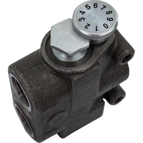
The Priority Flow Divider Valve from Buyers Products splits the oil from a single inlet into two separate flows, ensuring that your oil flow is maintained at the proper GMA regardless of load variations. One flow, the priority flow, is controllable and adjustable to your GPM needs using a knob on the valve. The remaining secondary oil can be used for another need -- at the same time -- without affecting the pressure of the priority flow. By splitting the flow in two, you can divert the secondary oil to a different operation while simultaneously ensuring you have the right GPM for your application. The valve can handle a maximum flow of 3000 PSI .
Specifications
| Material | Cast Iron |
|---|---|
| Maximum Flow Rate | 30 |
| Maximum Pressure | 3000 |
| Maximum Relief Pressure Setting | - |
| Number of Ports | 3 |
| Port Size | 1 NPTF |
Advanced Technical Overview: 1 Inch Priority Flow Divider Valve 30 GPM
The 1 Inch Priority Flow Divider Valve, engineered for robust performance up to 30 GPM, represents a critical component in advanced hydraulic systems requiring precise, load-independent flow management. This device excels in applications where a primary hydraulic function demands a consistent and prioritized flow rate, while simultaneously allowing for the utilization of excess flow for a secondary, non-critical operation. Constructed from durable cast iron and rated for a maximum operating pressure of 3000 PSI, this valve is designed for reliability and longevity in demanding industrial and mobile hydraulic environments.
Fundamental Principle of Operation: Pressure Compensation
At its core, the Priority Flow Divider Valve operates on the principle of pressure compensation. Unlike simple orifice-based flow controls, which are inherently sensitive to upstream and downstream pressure fluctuations, a pressure-compensated flow divider actively maintains a constant flow rate to the priority circuit, irrespective of variations in load pressure in either the priority or secondary circuits, or fluctuations in the inlet pressure (within operational limits). This is achieved through a finely tuned internal spool mechanism.
The valve features three distinct ports: an inlet port (P), a priority flow outlet port (CF), and a secondary or excess flow outlet port (EX). When pressurized fluid enters the inlet port, it encounters a sensing orifice and a movable spool. The pressure differential across this sensing orifice is directly proportional to the flow rate. This differential pressure acts on opposing ends of the spool, which is also influenced by a precisely calibrated spring and, in some designs, a manual adjustment mechanism.
The adjustable knob on the valve allows the operator to precisely set the desired flow rate for the priority circuit. This adjustment typically alters the spring force acting on the spool or changes the effective area of the sensing orifice. As the operator adjusts the knob, they are effectively calibrating the pressure differential required to achieve the target GPM for the priority flow. Once set, the spool constantly modulates its position to maintain this specific pressure drop across the sensing orifice, thereby ensuring a constant flow rate to the priority outlet.
Any fluid entering the valve beyond what is required for the set priority flow is directed to the secondary (EX) port. A critical feature of this design is the isolation of the priority flow from the secondary flow's pressure. The pressure compensation mechanism ensures that the priority flow remains unaffected by the load or pressure conditions in the secondary circuit. For instance, if the secondary circuit encounters a high-pressure spike or becomes unloaded, the priority flow will continue uninterrupted and at its precisely set rate. This independent operation is paramount for applications where consistent performance of the primary function is non-negotiable.
Technical Specifications and Their Systemic Implications
- Material: Cast Iron: The selection of cast iron for the valve body is a testament to its robust design. Cast iron offers excellent compressive strength, good damping characteristics, and superior resistance to wear and thermal fatigue, making it highly suitable for high-pressure hydraulic applications. Its inherent rigidity minimizes distortion under pressure, ensuring consistent internal clearances for optimal spool operation. Furthermore, cast iron provides good machinability, allowing for precise internal porting and critical surfaces necessary for accurate flow division.
- Maximum Flow Rate: 30 GPM: A maximum flow rate of 30 Gallons Per Minute (GPM) indicates the valve's capacity to handle substantial fluid volumes. This rating is critical for system designers as it defines the upper limit of the total flow that can be effectively managed and divided by the valve without excessive pressure drop or operational instability. When integrating into a hydraulic system, the pump's output and the maximum requirements of both the priority and secondary circuits must be considered in relation to this specification to prevent cavitation or inadequate flow to either function.
- Maximum Pressure: 3000 PSI: The 3000 PSI (Pounds per Square Inch) maximum pressure rating signifies the structural integrity and operational threshold of the valve. This specification ensures that the valve can safely withstand the peak pressures encountered in many industrial and mobile hydraulic systems without risk of structural failure or internal leakage. It is crucial that the system's operating pressure, including potential pressure spikes, remains below this maximum rating to guarantee system safety and component longevity.
- Number of Ports: 3: The three-port configuration (Inlet, Priority Outlet, Secondary Outlet) is standard for this type of flow divider. This explicit configuration simplifies plumbing and clearly defines the flow paths within the hydraulic circuit, reducing complexity in system design and troubleshooting.
- Port Size: 1 NPTF: The 1 NPTF (National Pipe Taper Fuel) port size is a critical interface specification. NPTF threads are designed to create a mechanical seal upon tightening, with the threads themselves forming a metal-to-metal seal, often without the need for additional sealants if properly installed. A 1-inch NPTF port size is appropriate for managing the specified 30 GPM flow rate, minimizing pressure drop across the ports and enabling robust connections for high-pressure applications. The tapered design ensures a secure and leak-free connection, which is vital in hydraulic systems where even minor leaks can lead to significant fluid loss and system inefficiency.
Advantages and System Benefits
The deployment of the 1 Inch Priority Flow Divider Valve offers a multitude of technical and operational advantages:
- Precision Flow Control: The primary benefit is the ability to provide a highly accurate and consistent flow rate to a critical hydraulic function. This precision is vital for applications requiring exact speeds, feed rates, or controlled motion, such as the operation of sensitive hydraulic motors, cylinders in machining processes, or synchronized movements in automated systems.
- Load-Independent Performance: The pressure compensation feature ensures that the priority flow is unaffected by pressure fluctuations in either the priority or secondary circuits. This characteristic is invaluable in dynamic systems where variable loads are common, guaranteeing that the primary function maintains its desired performance regardless of changes in ancillary operations.
- Enhanced System Efficiency: By effectively splitting a single pump's output, the valve allows for the simultaneous operation of two independent hydraulic functions without the need for multiple pumps. This optimizes power utilization, reduces energy consumption, and can lead to a more compact and cost-effective hydraulic power unit design. The excess flow, which might otherwise be directed over a relief valve and wasted as heat, is beneficially channeled to another task.
- Simplified System Design: Integrating a priority flow divider can significantly simplify the overall hydraulic circuit. Instead of complex manifold designs or multiple control valves, a single priority flow divider can manage the distribution of fluid from a single source, streamlining plumbing and reducing potential points of failure.
- Operational Flexibility: The adjustable nature of the priority flow rate via the knob provides operators with crucial flexibility to fine-tune machine performance in the field. This adaptability allows for optimization across various tasks or material types, enhancing the versatility of the hydraulic equipment.
- Reduced Heat Generation: By utilizing the secondary flow for productive work instead of bypassing it to the tank through a relief valve, the system generates less waste heat. Excessive heat is detrimental to hydraulic fluid and components, leading to accelerated wear and reduced system efficiency. Minimizing heat generation contributes to extended component life and reduced maintenance.
- Cost-Effectiveness: Avoiding the need for additional pumps, motors, or more elaborate control schemes for separate circuits can result in substantial cost savings in initial system build and ongoing operational expenses.
Typical Applications and Use Cases
The versatility and robust nature of this 1 Inch Priority Flow Divider Valve make it indispensable across a wide spectrum of hydraulic applications:
-
Mobile Hydraulics:
- Snowplows and Salt Spreaders: In winter maintenance vehicles, a priority flow divider can ensure a consistent flow to the plow lift/angle cylinders, guaranteeing precise control, while the secondary flow powers the salt spreader motor. This prevents fluctuations in spreader speed from affecting plow performance.
- Refuse Trucks: Critical functions like packer blade operation or body lift can be prioritized, with the secondary flow allocated to auxiliary functions like tailgate latches or tipper mechanisms.
- Utility Vehicles: For aerial lifts or bucket trucks, precise control of the boom and platform leveling systems (priority flow) is paramount for safety and efficiency, while tools like augers or saws (secondary flow) can operate concurrently.
- Agricultural Machinery: Tractors or combines can use priority flow for steering or critical implement control (e.g., header height), while secondary flow drives less critical functions like fan motors or auxiliary attachments.
-
Industrial Hydraulics:
- Machine Tools: In operations requiring precise feed rates, such as milling or grinding machines, the priority flow can control the tool advance, ensuring consistent cutting speeds. The secondary flow could power coolant pumps or chip conveyors.
- Material Handling Equipment: Conveyor systems requiring a constant belt speed for product flow can utilize priority flow for the drive motor, with secondary flow powering diverting gates or product sorters.
- Presses and Clamping Systems: Priority flow can be directed to the main press cylinder for controlled pressing speed, while secondary flow could operate clamping jaws or ejector pins.
- Test Benches: For hydraulic component testing, precise, controlled flow delivery (priority) is crucial for accurate results, while secondary flow can be used for ancillary test fixtures or fluid conditioning systems.
-
Construction Equipment:
- Mini Excavators/Skid Steers: Priority flow can be used for critical functions like boom lift or bucket curl, ensuring smooth and controlled movements, while secondary flow operates auxiliary attachments like grapples or breakers.
Installation, Maintenance, and System Integration Best Practices
Proper installation and routine maintenance are crucial for maximizing the performance and longevity of the Priority Flow Divider Valve:
- Mounting: The valve should be securely mounted in a location that provides easy access for adjustment and inspection. While specific orientation usually isn't critical for function, adhering to manufacturers' recommendations regarding mounting position can facilitate air bleeding and proper fluid drainage.
- Plumbing: All hydraulic lines connecting to the valve must be correctly sized to handle the maximum flow and pressure without excessive velocity or pressure drop. Use high-quality 1 NPTF fittings and ensure proper thread engagement and sealing practices to prevent leaks. Clear identification of inlet (P), priority (CF), and secondary (EX) ports is essential during plumbing to avoid incorrect connections that could lead to system malfunction or damage.
- Filtration: Hydraulic fluid cleanliness is paramount. Fine filtration (e.g., 10-micron nominal) should be maintained upstream of the flow divider to prevent contaminants from entering the valve. Contaminants can cause the internal spool to stick, leading to inconsistent flow division, premature wear, or complete valve failure. Regular monitoring and replacement of filter elements are critical.
- Fluid Compatibility: Use hydraulic fluid that meets the system's specifications and is compatible with the valve's internal components and seals. Proper viscosity is key for efficient operation across the expected temperature range.
- Adjustment Procedure: When setting the priority flow, it is recommended to use a calibrated flow meter in the priority circuit. The adjustment knob should be turned slowly and incrementally, observing the flow meter reading until the desired GPM is achieved. This ensures accurate calibration and prevents over-adjustment or hunting.
- Troubleshooting: Common issues include inconsistent priority flow (often due to contamination, leading to a sticking spool), reduced flow to both ports (indicating an issue with the pump or inlet restriction), or secondary flow affecting priority flow (suggesting internal leakage or spool wear). Regular system pressure and flow checks can help diagnose problems early.
Distinction from Other Flow Control Technologies
It is important to differentiate the priority flow divider from other flow control devices to appreciate its specific advantages:
- Fixed Orifices: A fixed orifice simply restricts flow, and the flow rate through it is highly dependent on the pressure differential across it. Changes in upstream or downstream pressure will directly alter the flow, offering no compensation. The priority flow divider, in contrast, actively maintains flow regardless of load changes.
- Bypass Flow Regulators: While also controlling flow, bypass regulators typically direct excess fluid back to the tank, often through a relief valve, thus wasting energy as heat. A priority flow divider utilizes the excess flow for productive work in a secondary circuit, enhancing efficiency.
- Proportional Valves: These offer highly precise, electronically controlled flow rates, often variable based on input signals. While more versatile, they are also significantly more complex, expensive, and require electronic control systems, whereas the priority flow divider offers robust, mechanical pressure compensation for fixed or manually adjustable priority flow.
Conclusion
The 1 Inch Priority Flow Divider Valve 30 GPM stands as an exemplary solution for hydraulic systems demanding reliable, load-independent flow distribution. Its robust cast iron construction, precise 30 GPM flow capacity, and high 3000 PSI pressure rating ensure durability and high performance. By providing a stable, adjustable priority flow while simultaneously making excess fluid available for secondary functions without mutual interference, this valve significantly enhances hydraulic system efficiency, control precision, and operational flexibility. For engineers and system integrators seeking to optimize hydraulic power utilization and ensure the consistent performance of critical functions, this priority flow divider valve represents a technically sound and economically advantageous component choice.