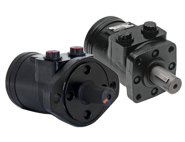
Char-Lynn Hydraulic Motors from Buyers Products are designed to be economical, efficient, compact, and powerful. They are a great solution for powering medium-duty applications like compressors, augers, winches, cranes, and spreaders. The motors have an industry-proven spool valve design combined with state-of-the-art gerotors. They excel at jobs that need a high degree of start-up torque or just the right mixture of torque and flow rate. Choose from a wide range of motors depending on your needs for flow rates, torque, and starting torque. Each model is available with either a 2-bolt or 4-bolt mount. The last digit of the part number (2 or 4) will indicate the number of bolts.
Specifications
| Compares To | 101-1001-009 |
|---|---|
| Displacement | 2.8 |
| Flow (Continuous) | 12 |
| Flow (Intermittent) | 14 |
| Input Mount Type | 4 Bolt |
| Material | Cast Iron |
| Maximum Case Pressure (Without Case Drain) | 1500 |
| Maximum Speed (Continuous) | 969 |
| Maximum Speed at Continuous Flow | 969 |
| Maximum Speed at Intermittent Flow | 1130 |
| Minimum Starting Torque (Continuous Pressure) | 520 |
| Minimum Starting Torque (Intermittent Pressure) | 720 |
| Pilot Diameter | 1.75 |
| Port Size | 1/2 NPT |
| Pressure ? Bar (Continuous) | 1800 |
| Pressure ? Bar (Intermittent) | 2400 |
| Shaft Keyway | 0.25 |
| Shaft Size | 1.00 |
| Shaft Type | Straight |
| Torque Rating (Continuous) | 650 |
| Torque Rating (Intermittent) | 720 |
Advanced Technical Overview: Hydraulic Motor with 4-Bolt Mount, NPT Threads, and 2.8 Cubic Inches Displacement
This detailed product description provides an in-depth technical analysis of the hydraulic motor offered by Buyers Products, specifically highlighting its robust design, precise engineering, and performance characteristics tailored for medium-duty industrial and mobile applications. Derived from the reputable Char-Lynn lineage, these motors are celebrated for their optimal balance of economy, efficiency, compactness, and power output, making them an indispensable component in demanding hydraulic systems.
Core Design Philosophy: Gerotor and Spool Valve Synergy
At the heart of this hydraulic motor's exceptional performance lies the synergistic integration of a state-of-the-art gerotor (GERotor for GEnerated ROTOR) power element and an industry-proven spool valve design. This combination is engineered to deliver superior hydraulic energy conversion, ensuring reliable and consistent operation even under challenging conditions.
The Gerotor Principle: Efficiency and High Starting Torque
The gerotor mechanism is a key component responsible for the motor's volumetric displacement and its ability to generate high torque. Comprising an inner rotor with N teeth and an outer rotor with N+1 teeth, this orbital motor design creates expanding and contracting chambers as the rotors rotate eccentrically within one another. Hydraulic fluid, supplied under pressure, enters these expanding chambers, forcing the inner rotor to rotate. As the chambers contract, the fluid is expelled through the motor's outlet port.
The specific displacement of this motor is 2.8 cubic inches per revolution. This figure represents the precise volume of hydraulic fluid required to complete one full rotation of the motor shaft. A smaller displacement motor, like this 2.8 in³ model, typically achieves higher speeds for a given flow rate while providing a well-balanced torque output suitable for its intended applications. The inherent design of the gerotor, characterized by its continuous engagement of multiple tooth profiles, minimizes internal leakage paths and maximizes volumetric efficiency, particularly beneficial for maintaining consistent speed and torque under varying loads. Furthermore, the large contact area between the inner and outer rotors contributes significantly to the motor's impressive starting torque capabilities, a critical factor for applications requiring immediate power upon activation, such as augers or winches that must overcome static friction.
The Spool Valve System: Precise Fluid Control and Commutation
Complementing the gerotor mechanism is an intelligently designed spool valve system. The primary function of the spool valve is to direct the high-pressure hydraulic fluid to the appropriate chambers of the gerotor element at precise moments, and simultaneously route the low-pressure exhaust fluid away. This commutation process is vital for smooth, continuous rotation and efficient power transfer.
The industry-proven nature of this spool valve design signifies years of refinement and optimization, resulting in a system that offers:
- Efficient Commutation: The timing and sequencing of fluid delivery and exhaust are meticulously controlled, minimizing pressure drops and energy losses during the transition between chambers. This contributes directly to the motor's overall efficiency.
- Reduced Internal Leakage: Tight tolerances and advanced sealing technologies within the spool valve prevent unwanted fluid bypass, ensuring that a maximum proportion of the input fluid energy is converted into mechanical work at the shaft.
- Durability and Reliability: The robust construction and material selection for the spool valve components, often hardened steel, provide excellent wear resistance and longevity, even when operating with contaminated hydraulic fluid or under pulsating pressure conditions.
- Smooth Operation: The controlled fluid transitions facilitated by the spool valve contribute to a remarkably smooth and quiet operation, reducing pulsations and vibrations that could impact the driven machinery or operator comfort.
Detailed Performance Specifications and Their Implications
Volumetric Displacement: 2.8 Cubic Inches
The motor’s displacement of 2.8 cubic inches (in³) per revolution is a fundamental parameter that dictates its torque and speed characteristics in conjunction with hydraulic pressure and flow. For every revolution of the output shaft, 2.8 cubic inches of hydraulic fluid must pass through the motor. This displacement, when multiplied by the effective hydraulic pressure, determines the theoretical torque output. This specific displacement positions the motor ideally for applications requiring a balance of rotational speed and torque for medium-duty tasks, providing agility without sacrificing the necessary power to overcome loads.
Torque Ratings: Power Under Load
Torque is the rotational force produced by the motor, a critical parameter for driving various applications. This motor exhibits impressive torque characteristics:
- Torque Rating (Continuous): 650 in-lb (inch-pounds). This represents the maximum torque the motor can consistently produce without exceeding its thermal or mechanical design limits over an extended period. Continuous operation at this torque level ensures longevity and reliable performance.
- Torque Rating (Intermittent): 720 in-lb. The motor can generate this higher torque for shorter durations or in cycles, allowing it to handle peak loads or momentary demands that exceed continuous ratings. This capability is vital for applications with fluctuating load requirements.
- Minimum Starting Torque (Continuous Pressure): 520 in-lb. This specifies the minimum torque available at the shaft when the motor is initially pressurized at its continuous operating pressure. A high starting torque is essential for initiating motion in heavily loaded systems, such as starting an auger filled with material or beginning to hoist a heavy load with a winch.
- Minimum Starting Torque (Intermittent Pressure): 720 in-lb. When subjected to intermittent pressure levels, the motor can deliver a higher starting torque, further enhancing its ability to break static friction and commence operation under severe initial loading.
The high starting torque inherent in the gerotor design, combined with these robust torque ratings, makes this motor particularly effective in overcoming static friction and inertia in challenging applications.
Flow Rates: Governing Speed
Hydraulic flow directly influences the motor’s rotational speed. The motor's specified flow rates are:
- Flow (Continuous): 12 GPM (gallons per minute). This is the sustained flow rate the motor can efficiently convert into rotational energy over extended periods.
- Flow (Intermittent): 14 GPM. For short durations, the motor can handle a higher flow rate, translating to increased speed for brief periods when maximum performance is required.
Understanding these flow rates is crucial for selecting an appropriately sized hydraulic pump to ensure the motor operates within its design parameters for optimal efficiency and lifespan.
Speed Characteristics: RPM Output
The motor's speed, measured in revolutions per minute (RPM), is directly proportional to the incoming flow rate and inversely proportional to its displacement, taking into account volumetric efficiency. The specifications are:
- Maximum Speed (Continuous) / Maximum Speed at Continuous Flow: 969 RPM. This is the highest rotational speed the motor can maintain continuously when supplied with its continuous flow rate.
- Maximum Speed at Intermittent Flow: 1130 RPM. This indicates the peak speed achievable during intermittent operation with the higher intermittent flow rate.
These speed ratings confirm the motor's capability to drive components requiring moderate to high rotational velocities, offering flexibility across a range of operational requirements.
Pressure Capabilities: System Power
Hydraulic pressure is the force applied to the fluid, directly correlating with the torque generated by the motor. The specified pressure ratings (assuming the "Bar" label in the table is a misprint and these values are in PSI, which is typical for such motor specifications and aligns with the given torque ratings):
- Pressure (Continuous): 1800 PSI. This is the maximum pressure the motor can withstand and operate efficiently under for continuous duty cycles.
- Pressure (Intermittent): 2400 PSI. The motor is designed to tolerate higher peak pressures for short durations, providing an additional margin for demanding tasks or transient pressure spikes.
These pressure ratings are indicative of the motor's robust construction and its ability to harness significant hydraulic power. Furthermore, the motor specifies a Maximum Case Pressure (Without Case Drain) of 1500 PSI. This parameter is critical. Many hydraulic motors incorporate an internal leakage path to lubricate internal components and cool the motor. If the internal pressure, or case pressure, exceeds this limit, it can compromise shaft seals and lead to premature failure. For applications where the return line pressure might approach or exceed 1500 PSI, or where there are significant pressure fluctuations, the implementation of an external case drain line is strongly recommended to relieve pressure and protect the motor's seals.
Physical and Interface Specifications
Input Mount Type: 4-Bolt Mount
The 4-bolt mount configuration specified for this model is a robust and widely adopted standard in hydraulic system integration. This mounting pattern offers superior stability and alignment compared to 2-bolt options, particularly advantageous for applications involving significant vibrational loads, shock, or precise shaft alignment requirements. The four evenly spaced bolts ensure a secure and rigid connection between the motor and the driven equipment or mounting bracket, minimizing stress concentrations and extending the operational life of the assembly. This makes it ideal for heavy-duty applications like winches, augers, and cranes where structural integrity and reliable attachment are paramount.
Port Size: 1/2 NPT Threads
The motor is equipped with 1/2 NPT (National Pipe Taper) threads for its hydraulic ports. NPT threads are a common choice for hydraulic connections due to their self-sealing characteristic. The tapered design allows the threads to wedge together upon tightening, creating a fluid-tight seal without the need for additional O-rings or gaskets on the thread itself, although thread sealant or tape is typically used for optimal sealing. The 1/2-inch nominal pipe size is suitable for the specified continuous and intermittent flow rates, ensuring minimal pressure drop across the ports and efficient fluid transfer to and from the gerotor element.
Pilot Diameter: 1.75 Inches
The 1.75-inch pilot diameter is a precision machined feature on the motor's mounting face. Its purpose is to ensure accurate concentric alignment of the motor with the mating component, such as a gearbox, pump, or bearing housing. Proper piloting is essential for preventing misalignment, which can lead to premature bearing wear, shaft seal damage, and excessive vibration, thereby extending the overall lifespan and efficiency of the integrated system.
Shaft Characteristics: Power Transmission
The motor features a 1.00-inch straight shaft with a 0.25-inch keyway. The straight shaft design is a versatile and commonly used configuration, allowing for easy coupling to various power transmission components like pulleys, sprockets, or flexible couplings. The 1.00-inch diameter provides ample strength to transmit the motor's rated torque outputs without deformation or failure. The 0.25-inch keyway is a critical element for securely transmitting rotational torque from the motor shaft to the driven component. A precisely machined key and keyway assembly prevents slippage between the shaft and the attached component, ensuring efficient and reliable power delivery. The use of a straight shaft and keyway simplifies maintenance and replacement procedures.
Material: Cast Iron Construction
The motor housing and critical structural components are constructed from high-grade cast iron. Cast iron is an excellent material choice for hydraulic motors due to its inherent properties:
- High Strength and Rigidity: Cast iron provides robust structural integrity, allowing the motor to withstand the high internal pressures and external forces encountered in hydraulic applications.
- Vibration Damping: The material’s microstructure helps to absorb and dampen vibrations, leading to smoother, quieter operation and reduced stress on surrounding components.
- Wear Resistance: Cast iron offers good wear resistance, contributing to the motor's longevity in demanding operational environments.
- Thermal Stability: It exhibits good thermal stability, helping to dissipate heat generated during operation and maintain consistent performance.
This durable construction ensures the motor's reliability and extended service life, even in harsh industrial or mobile environments.
Application Suitability and Advantages
The combination of a 2.8 cubic inch displacement, high starting torque, and robust construction makes this hydraulic motor exceptionally well-suited for a variety of medium-duty applications as outlined in the initial description:
- Compressors: Provides consistent power for efficient air or gas compression.
- Augers: The high minimum starting torque is crucial for initiating rotation when the auger is embedded in dense material, and the continuous torque ensures effective material handling.
- Winches: Excellent starting torque enables reliable lifting and pulling from a dead stop, while continuous torque and speed offer controlled and powerful operation.
- Cranes: Essential for precise and powerful lifting and lowering operations, where controlled speed and high torque are paramount.
- Spreaders: Delivers the necessary power and speed control for consistent material distribution.
The economic and efficient design, coupled with its compact footprint, allows for easier integration into existing systems or new designs where space may be a constraint without compromising on power or durability.
System Integration and Maintenance Considerations
To maximize the performance and longevity of this hydraulic motor, careful attention to system integration and maintenance is essential:
- Hydraulic Fluid Selection: Use only high-quality hydraulic fluid that meets the manufacturer's specifications for viscosity, temperature range, and additive package. Proper fluid ensures optimal lubrication, heat transfer, and protection against wear.
- Filtration: Maintain stringent fluid filtration to prevent contaminants from entering the motor. Particles as small as 5-10 microns can cause significant wear to the precision-machined components of the gerotor and spool valve, leading to reduced efficiency and premature failure.
- Heat Management: Ensure the hydraulic system has adequate cooling capacity to prevent fluid temperatures from exceeding recommended limits. Overheating can degrade hydraulic fluid, reduce component life, and decrease overall system efficiency.
- Pressure Relief: Implement appropriate pressure relief valves in the hydraulic circuit to protect the motor and other components from excessive pressure spikes.
- Case Drain Line: For applications where return line pressure might be elevated or fluctuating, installing a dedicated case drain line to the reservoir is crucial to prevent excessive case pressure and protect the motor's shaft seal.
Conclusion
The Hydraulic Motor from Buyers Products, featuring a 4-bolt mount, 1/2 NPT threads, and 2.8 cubic inches of displacement, represents a technically advanced and highly reliable solution for a broad spectrum of medium-duty hydraulic applications. Its meticulously engineered gerotor and spool valve system ensures high volumetric efficiency, exceptional starting torque, and smooth, consistent power delivery. Constructed from durable cast iron and designed with robust mounting and porting standards, this motor is built to withstand rigorous operating conditions while maintaining peak performance. By understanding its detailed specifications and adhering to best practices for hydraulic system integration and maintenance, operators can leverage this motor's full potential for long-term, efficient, and trouble-free operation, ultimately enhancing productivity and reducing operational costs.