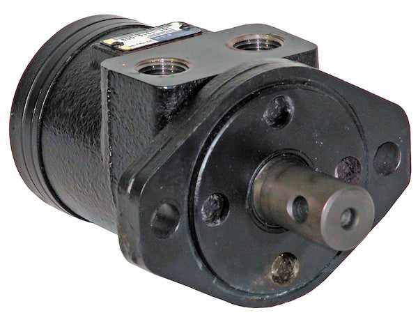
Char-Lynn Hydraulic Motors from Buyers Products are designed to be economical, efficient, compact, and powerful. They are a great solution for powering medium-duty applications like compressors, augers, winches, cranes, and spreaders. The motors have an industry-proven spool valve design combined with state-of-the-art gerotors. They excel at jobs that need a high degree of start-up torque or just the right mixture of torque and flow rate. Choose from a wide range of motors depending on your needs for flow rates, torque, and starting torque. Each model is available with either a 2-bolt or 4-bolt mount. The last digit of the part number (2 or 4) will indicate the number of bolts.
Specifications
| Compares To | 101-1319-009 |
|---|---|
| Displacement | 2.8 |
| Flow (Continuous) | 12 |
| Flow (Intermittent) | 14 |
| Input Mount Type | 2 Bolt |
| Material | Cast Iron |
| Maximum Case Pressure (Without Case Drain) | 1500 |
| Maximum Speed (Continuous) | 969 |
| Maximum Speed at Continuous Flow | 969 |
| Maximum Speed at Intermittent Flow | 1130 |
| Minimum Starting Torque (Continuous Pressure) | 520 |
| Minimum Starting Torque (Intermittent Pressure) | 720 |
| Pilot Diameter | 3.25 |
| Port Size | 1/2 NPT |
| Pressure ? Bar (Continuous) | 1800 |
| Pressure ? Bar (Intermittent) | 2400 |
| Shaft Keyway | Cross drilled |
| Shaft Size | 1.00 |
| Shaft Type | Straight |
| Torque Rating (Continuous) | 650 |
| Torque Rating (Intermittent) | 720 |
Comprehensive Technical Overview: Hydraulic Spinner Motor with 2-Bolt Mount and Cross-Drilled Shaft
This detailed technical description delves into the design, operational principles, performance characteristics, and application suitability of the hydraulic spinner motor, specifically highlighting its 2-bolt mount and cross-drilled shaft configuration. Manufactured to exacting standards, this Char-Lynn style hydraulic motor, comparable to the 101-1319-009, from Buyers Products represents an optimal solution for a broad spectrum of medium-duty mobile and industrial hydraulic applications, where efficiency, power density, and robust construction are paramount.
Fundamental Operating Principles: Gerotor and Spool Valve Technology
At the core of this hydraulic motor's exceptional performance lies the combination of a precision-engineered gerotor gear set and an industry-proven spool valve distribution system. This design paradigm is integral to its ability to convert hydraulic energy from pressurized fluid into reliable mechanical rotational energy, delivering a consistent and powerful output.
The Gerotor Gear Set
The gerotor (Generated Rotor) principle is a positive displacement mechanism characterized by an inner rotor and an outer rotor. The inner rotor has one fewer lobe than the outer rotor, and both are concentrically mounted but rotate eccentrically to each other. As hydraulic fluid is introduced, it fills the expanding cavities between the lobes of the inner and outer rotors. The pressure of the fluid forces the rotors to turn, progressively sweeping the fluid through the motor. This continuous expansion and contraction of fluid chambers generate the rotational motion of the output shaft.
Key advantages of the gerotor design include:
- High Volumetric Efficiency: The precise meshing of the rotors minimizes internal leakage, ensuring that a significant portion of the input flow is converted into mechanical work.
- Smooth Operation: The continuous engagement of multiple lobes results in minimal torque ripple, providing a remarkably smooth and consistent rotational output, even at low speeds.
- Compact Design: Gerotor motors offer excellent power density, meaning they can deliver substantial torque from a relatively small physical envelope, crucial for space-constrained applications.
- High Starting Torque: This inherent characteristic allows the motor to overcome significant static loads with ease, a critical feature for applications like augers, winches, and spreaders that require immediate, powerful engagement.
- Durability: The robust nature of the gerotor elements, coupled with proper material selection, contributes to a long operational life under demanding conditions.
The Spool Valve Distribution System
The spool valve acts as the hydraulic commutator for the gerotor set. It precisely directs the incoming pressurized hydraulic fluid to the expanding chambers and exhausts the spent fluid from the contracting chambers. This synchronous valving ensures efficient and timed fluid distribution to optimize the gerotor's operation. The industry-proven spool valve design in this motor is engineered for reliability, minimizing internal leakage pathways and maximizing pressure utilization. This precise control over fluid flow is instrumental in achieving the desired balance of torque and flow rate, allowing for versatile performance across various operational requirements.
Material and Construction: Cast Iron Durability
The motor's housing is constructed from high-grade cast iron. This material choice is deliberate, offering several distinct advantages:
- Superior Strength and Rigidity: Cast iron provides exceptional mechanical strength, enabling the motor to withstand high internal pressures and external stresses without deformation, ensuring component alignment and operational integrity.
- Excellent Vibration Damping: The inherent properties of cast iron help to absorb and dampen vibrations, leading to smoother operation, reduced noise, and extended lifespan for both the motor and associated machinery.
- Effective Heat Dissipation: Cast iron possesses good thermal conductivity, aiding in the dissipation of heat generated during operation, which is crucial for maintaining optimal fluid temperatures and preventing thermal degradation of seals and hydraulic fluid.
- Corrosion Resistance: While not fully impervious, cast iron offers a good level of resistance to various environmental factors, particularly when treated or coated, contributing to the motor's longevity in diverse working environments.
This robust construction ensures that the motor maintains its performance integrity in harsh industrial and mobile environments.
Detailed Performance Specifications and Their Implications
Understanding the technical specifications is key to selecting the appropriate hydraulic motor for a given application. This motor's specifications reveal its capabilities and ideal operational parameters.
Displacement (2.8 cu. in./rev)
Displacement refers to the volume of hydraulic fluid required to rotate the motor output shaft by one complete revolution. A displacement of 2.8 cubic inches per revolution signifies the motor's size in terms of its ability to convert fluid volume into mechanical rotation. Lower displacement motors typically achieve higher speeds at a given flow rate but produce less torque, while higher displacement motors produce more torque at lower speeds. This 2.8 cu. in./rev displacement positions the motor firmly within the medium-duty category, balancing speed and torque output effectively for its intended applications.
Flow Rates (Continuous: 12 GPM, Intermittent: 14 GPM)
Flow rate dictates the maximum speed at which the motor can operate. A continuous flow rate of 12 GPM (Gallons Per Minute) indicates the sustained input flow for prolonged operation without overheating or undue wear. The intermittent flow rate of 14 GPM allows for short bursts of higher performance when transient demands require increased speed or power. Proper system design must account for these limits to ensure motor longevity and optimal performance.
Pressure Ratings (Continuous: 1800 PSI, Intermittent: 2400 PSI)
Pressure is directly proportional to the torque output of a hydraulic motor. A continuous pressure rating of 1800 PSI (Pounds per Square Inch) defines the maximum pressure the motor can safely endure during prolonged operation, directly influencing the continuous torque output. The intermittent pressure rating of 2400 PSI allows the motor to generate higher torque for brief periods, such as during start-up or when encountering temporary overloads. Exceeding these pressure limits, particularly the intermittent rating, can lead to premature wear or catastrophic failure.
Maximum Case Pressure (Without Case Drain: 1500 PSI)
The maximum case pressure (without a case drain) of 1500 PSI is a critical parameter. It refers to the permissible pressure within the motor's housing. In hydraulic motors without an external case drain port, internal leakage fluid accumulates in the motor's casing before being directed back to the low-pressure side of the system (often through the motor's outlet port). This internal pressure must not exceed 1500 PSI to prevent damage to shaft seals and internal components. For systems operating closer to this limit, or experiencing high pressure spikes, the inclusion of a dedicated case drain line, though not standard for this specific model, might be considered in alternative configurations or system designs to ensure seal integrity and extend motor life.
Speed Ratings (Continuous: 969 RPM, Intermittent: 1130 RPM)
The maximum speed at continuous flow is 969 RPM, while the intermittent speed can reach 1130 RPM. These figures are derived from the motor's displacement and the respective flow rates. Gerotor motors are known for their excellent low-speed performance, delivering consistent torque even at very slow rotational speeds, while still being capable of achieving moderate to high speeds suitable for spinner applications.
Torque Ratings (Continuous: 650 lb-in, Intermittent: 720 lb-in)
Torque is the rotational force produced by the motor. A continuous torque rating of 650 lb-in (pound-inches) indicates the maximum torque the motor can sustain indefinitely without excessive heat generation or wear. The intermittent torque rating of 720 lb-in allows for higher torque output over short durations. This motor's robust torque output, combined with its high starting torque capabilities (Minimum Starting Torque: Continuous Pressure 520 lb-in, Intermittent Pressure 720 lb-in), makes it exceptionally well-suited for applications that demand significant force to initiate motion or overcome sudden resistance.
Mechanical Integration: 2-Bolt Mount and Cross-Drilled Shaft
The physical interface of a hydraulic motor is as crucial as its internal mechanics. This motor features a standard 2-bolt mount and a specialized cross-drilled straight shaft, designed for secure and reliable integration.
2-Bolt Input Mount Type (SAE A-Mount Standard)
The 2-bolt mount, specifically characterized by a 3.25-inch pilot diameter, adheres to the SAE A-mount standard. This widely recognized industrial standard ensures interchangeability and compatibility with a vast array of hydraulic pumps, gearboxes, and other components. The two mounting bolts provide a robust and secure connection between the motor and the driven equipment or mounting bracket. This configuration is compact and suitable for applications where space is a consideration and the radial and axial loads are within the design parameters for a two-bolt pattern.
Straight Shaft with Cross-Drilled Keyway (1.00-inch Diameter)
The motor features a 1.00-inch diameter straight shaft. Straight shafts are preferred for their simplicity, ease of coupling, and ability to transmit torque efficiently when properly keyed. The inclusion of a cross-drilled keyway is a significant design enhancement. While a standard keyway transmits rotational torque, the cross-drilling provides an additional, highly secure method for attaching components to the shaft. This typically involves the insertion of a pin or bolt through the drilled hole, which then passes through a corresponding hole in the mounted component (e.g., a pulley, sprocket, or coupler hub). This design offers several advantages:
- Enhanced Axial Retention: The cross-drilled pin prevents axial movement of the attached component along the shaft, eliminating the need for retaining rings or set screws that can loosen over time, especially in high-vibration environments.
- Positive Torque Transfer: While the keyway handles the primary rotational torque, the cross-drilled pin offers an additional point of positive engagement, reinforcing the connection and reducing the risk of key shear or slippage under extreme or shock loads.
- Simplified Assembly: In some cases, a cross-drilled pin can simplify mounting procedures by offering a direct, robust connection point.
This shaft configuration is particularly beneficial for spinner applications where precise rotational alignment and secure attachment of the spinner disc or impeller are critical, often subjected to radial forces and varying loads.
Versatile Application Spectrum
The characteristics of this hydraulic spinner motor make it exceptionally well-suited for a diverse range of medium-duty applications across agricultural, construction, utility, and municipal sectors:
- Spreaders (Salt, Sand, Fertilizer): The motor's controlled speed, robust torque, and cross-drilled shaft for secure impeller attachment are ideal for accurately dispensing materials. Its ability to operate smoothly at varying speeds allows for precise control over spread patterns and rates, crucial for effective material distribution.
- Augers (Grain, Earth, Post-Hole Diggers): The high starting torque (520-720 lb-in) is critical for breaking loose compacted materials and initiating rotation under heavy loads. The continuous and intermittent torque ratings ensure sustained drilling or conveying capability, making it suitable for agricultural grain augers, earth drills, and post-hole diggers.
- Winches (Light to Medium Duty): For winching applications on utility vehicles, trailers, or small cranes, the motor provides the necessary torque for lifting and pulling. The precise control offered by the gerotor design allows for smooth starts and stops, reducing shock loads on cables and structures.
- Cranes (Smaller Articulating & Knuckleboom): In the context of smaller hydraulic crane systems, this motor can power various functions such as slew drives, auxiliary winches, or boom extension mechanisms, where controlled, powerful rotation is required.
- Compressors (Hydraulically Driven): For mobile applications requiring compressed air, this motor can efficiently drive the compressor head, offering a compact and reliable power source, especially in scenarios where a PTO drive is unavailable or impractical.
- Conveyors and Feeders: In agricultural or material handling systems, the motor's consistent speed and torque can drive conveyor belts or feeder mechanisms, ensuring a steady flow of materials.
- Mixers: For small-scale concrete mixers, feed mixers, or chemical blenders, the motor provides the necessary power to rotate mixing drums or impellers, handling the viscous and often variable loads associated with mixing.
System Integration and Maintenance Considerations
Proper integration and routine maintenance are vital to maximizing the lifespan and performance of this hydraulic motor.
Hydraulic Fluid and Filtration
The selection of hydraulic fluid is paramount. It must meet the manufacturer's specifications for viscosity, anti-wear properties, and operating temperature range. Consistent and proper fluid filtration is equally critical to prevent abrasive wear on the precision components of the gerotor and spool valve. Contaminants are the leading cause of hydraulic component failure.
System Pressure and Flow Management
The hydraulic system must be designed to deliver the specified flow rates and pressures to the motor without exceeding its maximum ratings. Relief valves should be correctly sized and set to protect the motor from over-pressurization, particularly during intermittent load spikes. Flow control valves may be used to regulate motor speed, ensuring optimal operation for the specific application.
Heat Management
Hydraulic systems generate heat. Adequate reservoir sizing and, if necessary, hydraulic fluid coolers should be employed to maintain the fluid within its optimal operating temperature range. Excessive heat accelerates fluid degradation and can damage seals and internal motor components.
Mounting and Alignment
Correct mounting, utilizing the 2-bolt pattern, is essential to prevent misalignment stresses on the motor shaft and bearings. The straight shaft and cross-drilled keyway facilitate a secure connection, but proper alignment of the driven component (e.g., pulley, gearbox input) is still critical to avoid premature bearing wear or shaft fatigue.
Routine Maintenance
Regular inspection of hydraulic lines for leaks, checking fluid levels and quality, and periodic filter replacement are fundamental maintenance practices. Monitoring motor performance for unusual noise, vibration, or reduced output can help identify potential issues before they lead to significant downtime.
Conclusion
The hydraulic spinner motor with its 2-bolt mount and cross-drilled shaft, a Char-Lynn style unit from Buyers Products, represents a robust and versatile power solution. Its economical nature, combined with the efficient and powerful operation derived from its state-of-the-art gerotor and spool valve design, makes it an excellent choice for medium-duty applications requiring high start-up torque and reliable performance. From the precise mechanical integration afforded by its standard mounting and specialized shaft to its durable cast iron construction and comprehensive performance envelope, this motor is engineered to deliver sustained, effective power in demanding environments, ensuring long-term operational excellence for a wide range of industrial and mobile machinery.