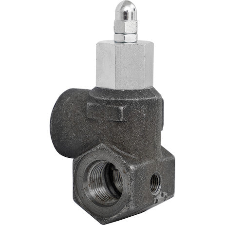
Buyers Products In-Line Relief Valve provides pressure relief to specific functions in your truck's hydraulic operations. Choose from a range of preset pressure ratings from 1650 to 2500 PSI.
Specifications
| Material | Cast Iron |
|---|---|
| Maximum Body Pressure | 3000 |
| Maximum Flow Rate | 30 |
| Maximum Pressure | 3000 |
| Maximum Relief Pressure Setting | 1501 |
| Number of Ports | 3 |
| Port Size | 3/4 NPTF |
The #12 SAE In-Line Relief Valve from Buyers Products, engineered for a robust 30 GPM flow rate, represents a critical component in ensuring the safety, longevity, and optimal performance of hydraulic systems, particularly within the demanding environment of truck-mounted equipment. This comprehensive overview delves into the technical specifications, operational principles, and multifaceted applications of this essential hydraulic device, illustrating its indispensable role in modern mobile hydraulics.
Hydraulic systems are inherently powerful, converting mechanical energy into fluid power to perform heavy-duty tasks. However, this immense power, if not meticulously controlled, can lead to catastrophic failures, equipment damage, and significant safety hazards. Overpressure conditions, arising from various operational scenarios such as sudden load changes, actuator stalling, or faulty system components, pose a constant threat. The primary function of a hydraulic relief valve is to act as a fail-safe mechanism, diverting excess fluid flow to the reservoir whenever system pressure exceeds a predetermined threshold. This preventive action safeguards the pump, actuators (cylinders and motors), hoses, fittings, and other delicate components from undue stress and potential rupture. The Buyers Products In-Line Relief Valve is specifically designed to provide localized, precise pressure relief to individual functions or critical sections within a larger hydraulic circuit, offering a targeted layer of protection.
Technical Specifications and Their Implications:
SAE #12 In-Line Design: The "#12 SAE" designation refers to the port size standard, indicating a specific thread and sealing configuration compliant with SAE (Society of Automotive Engineers) J1926/1 standard. SAE straight thread O-ring boss ports are widely regarded in the hydraulic industry for their superior sealing integrity compared to tapered thread connections. The O-ring provides a robust, leak-free seal that resists vibration and pressure fluctuations, which are prevalent in mobile applications. A #12 SAE port typically corresponds to a 3/4-inch nominal hose or tube size, ensuring compatibility with a broad range of hydraulic plumbing components. The "In-Line" aspect signifies its physical form factor and installation method; it is designed to be directly inserted into a pressure line, facilitating straightforward integration into existing or new hydraulic circuits without requiring specialized manifold blocks. This design approach simplifies plumbing, reduces potential leak points, and often offers a more compact solution for localized pressure management.
Maximum Flow Rate: 30 GPM (Gallons Per Minute): A maximum flow rating of 30 GPM is a critical parameter, defining the volumetric flow capacity the valve can safely handle without excessive pressure drop or erosion. In practical terms, this indicates that the valve is suitable for applications involving medium-to-high flow rates, typical of many truck-mounted hydraulic functions such as snowplow lift/angle, medium-sized dump body actuation, or certain auxiliary functions on refuse trucks. Selecting a relief valve with an adequate flow rating is paramount. An undersized valve will experience excessive internal velocity, leading to turbulent flow, increased heat generation, and premature wear, in addition to struggling to relieve pressure effectively. Conversely, an oversized valve, while not detrimental to performance, may add unnecessary cost and bulk. The 30 GPM rating positions this valve as a versatile choice for a wide array of mobile hydraulic applications where fluid power requirements demand efficient and unhindered flow up to this limit.
Preset Pressure Ratings: 1650 to 2500 PSI: The provision for preset pressure ratings ranging from 1650 PSI to 2500 PSI offers tailored protection options for diverse hydraulic circuits. A preset valve ensures that the relief pressure is accurately established at the factory, minimizing the need for on-site adjustment and reducing the risk of improper calibration. This range accommodates a significant portion of typical operating pressures found in truck hydraulic systems, allowing engineers and technicians to select a valve that closely matches the maximum permissible pressure for a specific actuator or circuit branch. For instance, a function requiring less force or operating with lighter components might use a 1650 PSI setting, while heavier-duty applications or those demanding higher force output might leverage the 2500 PSI setting. The precision of these factory presets is crucial for reliable operation, preventing nuisance tripping at normal operating pressures while ensuring immediate response to overpressure conditions.
Maximum Body Pressure and Maximum Pressure: 3000 PSI: The specifications indicate a Maximum Body Pressure of 3000 PSI and a general Maximum Pressure of 3000 PSI. These figures represent the absolute maximum static pressure the valve body and internal components can withstand without structural failure or permanent deformation. It is imperative that the relief valve's set pressure, even at its highest (2500 PSI in this case), remains comfortably below the maximum body pressure. This inherent safety margin of 500 PSI (3000 PSI max body - 2500 PSI max relief setting) is critical. It accounts for pressure spikes, transient surges, and the inherent variability in hydraulic systems, ensuring that even under extreme, momentary load conditions, the valve body itself remains structurally sound. Operating within these specified limits is fundamental to the long-term reliability and integrity of both the valve and the entire hydraulic system.
Material: Cast Iron: The choice of cast iron for the valve body is a testament to its robust engineering for demanding hydraulic applications. Cast iron offers an excellent balance of strength, rigidity, and cost-effectiveness. Key advantages include:
- High Compressive Strength: Cast iron exhibits superior compressive strength, making it ideal for containing high-pressure hydraulic fluids.
- Damping Properties: Its inherent material structure provides good vibration damping, which is beneficial in mobile applications where mechanical vibrations are common, potentially reducing noise and component fatigue.
- Machinability: Cast iron is relatively easy to machine, allowing for the precise internal geometries required for efficient valve operation.
- Corrosion Resistance: While not as corrosion-resistant as stainless steel, cast iron, when properly coated or used with appropriate hydraulic fluids, provides sufficient protection against common environmental elements encountered in truck operations.
- Thermal Stability: It maintains its mechanical properties across a wide range of operating temperatures typical of hydraulic systems.
Number of Ports: 3: The designation of "3 ports" for an in-line relief valve is highly significant, indicating its specific functional capability within a circuit. In the context of an in-line relief valve providing "pressure relief to specific functions," a 3-port configuration typically implies:
- Inlet (P) Port: Connects to the pressure line supplying fluid to the specific hydraulic function being protected.
- Outlet (A) Port: Connects to the actuator (cylinder or motor) or the sub-circuit that requires pressure limitation. This port carries the pressure-limited flow.
- Tank (T) Port: Connects directly to the hydraulic reservoir (tank). This is the path for excess fluid that is relieved from the inlet port when the set pressure is exceeded.
Port Size: 3/4 NPTF: The 3/4 NPTF port size refers to a 3/4-inch National Pipe Taper Fuel thread. NPTF threads are designed to create a mechanical seal by the deformation of the threads themselves upon tightening, ideally eliminating the need for sealant (though sealants are often used for added security). While SAE O-ring boss ports generally offer superior sealing for high-pressure, vibration-prone environments, NPTF connections are still widely used due to their commonality, cost-effectiveness, and ease of assembly with standard pipe fittings. For an in-line relief valve designed for 30 GPM flow, a 3/4-inch port size is appropriately matched, providing sufficient cross-sectional area to minimize flow restriction and pressure drop while maintaining adequate thread engagement for pressure containment. The selection of 3/4 NPTF for this valve indicates a design intended for broad compatibility with existing hydraulic systems and readily available components in the market.
Operational Principles:
The Buyers Products In-Line Relief Valve typically operates on a direct-acting principle, though pilot-operated variants exist for higher flow or more precise control. A direct-acting relief valve consists of a spring-loaded poppet or ball held against a seat. When the pressure at the inlet port (P) overcomes the force exerted by the spring, the poppet lifts off its seat, allowing fluid to flow from the inlet to the tank port (T). The "cracking pressure" is the pressure at which the valve first begins to open and pass a small, detectable flow. As the pressure continues to rise, the valve opens further until the "full flow pressure" is reached, at which point the valve passes its maximum rated flow (30 GPM) while maintaining the set relief pressure. Once the system pressure drops below the reseat pressure (which is typically slightly lower than the cracking pressure due to hysteresis), the spring force re-seats the poppet, closing the valve and stopping the flow to the tank. The preset nature of this valve means the spring compression is factory-adjusted to achieve the desired cracking and full flow pressures within the 1650-2500 PSI range, ensuring consistent and reliable performance.
Applications in Truck Hydraulics:
The specific function of providing pressure relief to individual circuits makes this valve invaluable across a spectrum of truck-mounted hydraulic applications:
- Snow and Ice Control Equipment: For snowplows, sand/salt spreaders, and de-icing sprayers, this valve can protect individual cylinder circuits (e.g., plow lift, angle, wing articulation) from shock loads encountered when hitting obstacles or during sudden directional changes, preventing damage to cylinders, hoses, and the plow structure itself.
- Dump Bodies and Trailers: In dump truck and trailer systems, an in-line relief valve can be strategically placed to protect the hoist cylinder(s) from overpressure caused by external forces when lowering the bed onto uneven terrain, or internal pressure spikes during rapid changes in load distribution.
- Refuse Collection Vehicles: Compactors, lifters, and ejector panels in garbage trucks experience immense and variable loads. This valve can protect specific compaction cylinders or lifter mechanisms from damage due to jams or excessive resistance, prolonging their operational life and preventing costly downtime.
- Wreckers and Rollback Carriers: For the boom, winch, and deck lift cylinders on tow trucks and rollback carriers, precise pressure limitation is essential. Overloading can occur when lifting heavy vehicles or during recovery operations. An in-line relief valve ensures these critical components operate within their safe working pressure, preventing structural damage and enhancing safety.
- Lift Gates and Cranes: On commercial vehicles equipped with hydraulic lift gates or small articulating cranes, this valve can protect the lift and tilt cylinders from overpressure conditions that might arise from improper loading, sudden drops, or external impacts, ensuring smooth and safe operation.
- Utility and Service Trucks: For aerial lifts, trenching equipment, and various auxiliary tools powered by the truck's hydraulic system, targeted relief valves are crucial for protecting sensitive attachments and ensuring operator safety.
Benefits and Advantages:
The integration of the Buyers Products In-Line Relief Valve offers a multitude of tangible benefits for hydraulic systems and their operators:
- Enhanced Safety: By preventing excessive pressure buildup, the valve significantly reduces the risk of hose rupture, component failure, and fluid leaks, thereby safeguarding personnel and preventing environmental contamination.
- Component Longevity: Protecting critical components like pumps, cylinders, motors, and control valves from overpressure directly extends their operational lifespan, reducing wear and tear and mitigating the need for frequent repairs or replacements.
- System Reliability and Uptime: A protected system is a reliable system. By actively preventing failures, the valve contributes to consistent operation and maximizes vehicle uptime, which is crucial for revenue-generating commercial vehicles.
- Cost Reduction: Preventing catastrophic failures translates into substantial cost savings by avoiding expensive component replacements, emergency repairs, and lost productivity due to downtime.
- Optimized Performance: By ensuring pressure remains within safe and efficient parameters, the valve indirectly supports the smooth and predictable operation of hydraulic actuators, contributing to better overall machine performance.
- Simplified Troubleshooting: In cases of hydraulic malfunction, the proper functioning of a relief valve can aid in diagnostics by confirming that overpressure protection is in place, allowing technicians to focus on other potential issues.
- Compliance with Standards: Adherence to proper pressure control protocols, facilitated by reliable relief valves, helps systems comply with industry safety standards and regulations.
Installation and Maintenance Considerations:
Proper installation of the In-Line Relief Valve is critical for its effective operation. It should be plumbed directly into the pressure line feeding the specific function it is intended to protect, with its tank port connected via a low-pressure return line directly to the reservoir. Care must be taken to ensure clean fluid conditions, as contaminants can cause the poppet to stick or the seat to wear, compromising the valve's integrity and set pressure. Regular inspection for external leaks and ensuring that the return line to the tank is unobstructed are essential maintenance practices. While the preset nature of this valve minimizes the need for field adjustments, understanding its operational parameters and periodically verifying its performance as part of a comprehensive maintenance schedule can ensure continued peak performance.
Engineering and Design Philosophy:
The Buyers Products #12 SAE In-Line Relief Valve embodies a design philosophy centered on durability, precision, and ease of integration. The use of cast iron speaks to a commitment to robust construction, capable of withstanding the harsh realities of mobile hydraulic applications. The meticulous factory presets reflect a dedication to precision engineering, ensuring that each valve performs reliably within its specified pressure range. This product is not merely a component; it is a vital safety and performance enhancer, meticulously crafted to meet the rigorous demands of the commercial trucking industry. Its compact, in-line form factor, combined with the proven reliability of SAE J1926/1 ports (and 3/4 NPTF for the return/relief path, if configured as such), makes it an adaptable solution for a wide range of hydraulic circuit designs. The selection of a 30 GPM flow rate ensures it can handle substantial fluid volumes without compromising pressure integrity, making it a cornerstone for efficient and safe hydraulic power management.
In conclusion, the #12 SAE In-Line Relief Valve 30 GPM from Buyers Products is an indispensable element for any commercial truck hydraulic system demanding precise, localized pressure control. Its robust cast iron construction, high flow capacity, reliable preset pressure options, and strategically designed 3-port configuration make it an optimal choice for protecting valuable hydraulic components, enhancing operational safety, and maximizing the overall longevity and performance of truck-mounted equipment. Investing in such a meticulously engineered relief valve is not just about compliance; it is about ensuring the enduring reliability and efficiency of critical mobile hydraulic operations.