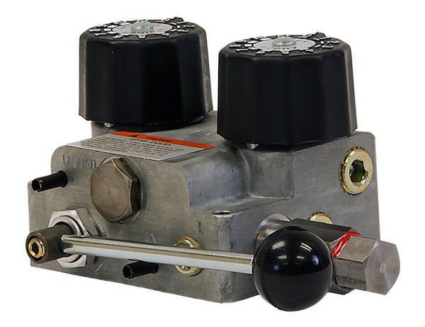
The Dual Flow Hydraulic Spreader Valve from Buyers Products is compact and easy to install, with a durable aluminum body. It features a built-in on/off control lever, system relief, and pressure compensation. Flow for each operation is easy to adjust, with two detent knobs that each feature 11 positive positions. Choose from a 7/15 GPM or a 10/30 GPM model to meet your needs.
Specifications
| Auger/Chain Flow Rate Max (GPM) | 30 |
|---|---|
| Auger/Chain Flow Rate Max (LPM) | 115 |
| Auger/Chain Port | 3/4 NPT |
| Flow (GPM) | 40 |
| Flow (LPM) | 153 |
| Functions Supported | Spinner/Auger |
| GPS Capable? | No |
| GPS Included? | No |
| Included Control Type | Manual |
| Inlet Port | 3/4 NPT |
| Load Sensing Port | - |
| Main Relief Setting | 1500 |
| Mount Type | Base |
| Number of Ports | 4 |
| Pre-Wet Supported? | No |
| Pressure | 2000 |
| Pressure (Bar) | 140 |
| Relief Cartridge Setting | 1500 |
| Single or Dual Flow | Dual |
| Spinner Flow Rate Max (GPM) | 10 |
| Spinner Flow Rate Max (LPM) | 115 |
| Spinner Port | 1/2 NPT |
| Tank Port | 3/4 NPT |
| Type | Fixed Displacement |
| What's Included | Valve Only |
The 3/4 Inch NPT Dual Flow Hydraulic Spreader Valve, specifically the 10-30 GPM model, represents a critical component in advanced material spreading systems. Engineered for precision and robust performance, this valve provides essential hydraulic control for diverse applications, ranging from winter road maintenance with salt and sand to agricultural broadcasting of fertilizers and seeds. Its design focuses on integrating functionality, durability, and user-friendliness, ensuring optimal operation in demanding environments.
At its core, this valve facilitates dual-flow capability, meaning it can independently control two separate hydraulic circuits from a single input source. In the context of a spreader, these typically correspond to the auger/chain conveyor system and the spinner mechanism. The auger/chain is responsible for delivering the spreading material from the hopper to the spinner, while the spinner disperses the material across the target area. Independent control over these two functions is paramount for achieving precise and consistent material distribution, which directly impacts efficiency, material conservation, and environmental compliance.
The specified flow rates of 10-30 GPM refer to the adjustable range for the two distinct outputs. Specifically, this model provides up to 10 GPM for the spinner function and up to 30 GPM for the auger/chain mechanism. This wide operational window allows operators to fine-tune material delivery and spread pattern based on factors such as material type (e.g., fine sand vs. coarse rock salt), vehicle speed, application density requirements, and environmental conditions. The ability to precisely manage these flows is a hallmark of an effective spreading system, preventing under-application or over-application of materials.
Technical Deep Dive into Key Features and Specifications
Dual Flow Functionality: Precision at Work
The "Dual Flow" designation signifies the valve's capability to deliver two distinct, independently adjustable hydraulic flows. For spreader applications, this translates directly to simultaneous, granular control over both the material conveying system (auger or chain) and the material broadcasting system (spinner). The benefits are substantial:
- Optimized Material Usage: By precisely controlling both the rate at which material exits the hopper and the speed at which it is spread, waste is minimized. This is particularly crucial for expensive spreading agents or environmentally sensitive applications.
- Consistent Spread Pattern: Independent adjustment allows operators to maintain a consistent spread width and density, regardless of variations in vehicle speed or material characteristics. For example, a higher auger/chain flow may be needed for heavier materials, while spinner speed can be adjusted to match desired spread width.
- Enhanced Efficiency: Operators can react in real-time to changing conditions, such as varying terrain, wind speed, or target application rates, without compromising the integrity of the spread.
The 10/30 GPM model specifically caters to systems requiring a max of 10 GPM for the spinner and up to 30 GPM for the auger/chain. This asymmetry in flow allocation is typical, as augers and chains often demand higher volumetric flow rates to move bulk material efficiently, while spinners, though high-speed, may require less flow for rotational power.
NPT Threading and Port Configuration
The "3/4 Inch NPT" in the title refers to the National Pipe Taper thread standard used for the main inlet, auger/chain, and tank ports. NPT connections are widely adopted in hydraulic systems due to their robust mechanical strength and effective sealing properties when properly assembled with sealant tape or compound. The tapered thread design allows for a mechanical interference fit, which, combined with sealant, creates a leak-tight connection crucial for high-pressure hydraulic applications.
- Inlet Port (3/4 NPT): This is where pressurized hydraulic fluid enters the valve from the pump. A 3/4-inch diameter is adequate for the specified total flow of up to 40 GPM (153 LPM), ensuring minimal pressure drop at the inlet.
- Auger/Chain Port (3/4 NPT): This port directs flow to the hydraulic motor driving the auger or chain. The 3/4-inch size is designed to accommodate the higher flow rates (up to 30 GPM) typically required for these material handling mechanisms.
- Spinner Port (1/2 NPT): This port directs flow to the hydraulic motor powering the spinner. The smaller 1/2-inch NPT size is appropriately matched to the lower maximum flow rate of 10 GPM for the spinner, optimizing cost and space without compromising performance.
- Tank Port (3/4 NPT): This port serves as the return line for hydraulic fluid back to the reservoir. Its 3/4-inch size ensures that return flow is not restricted, preventing backpressure buildup which could lead to system inefficiencies or overheating.
The four-port configuration (Inlet, Tank, Auger/Chain, Spinner) is standard for this type of dual-function hydraulic valve, ensuring a straightforward and logical integration into existing or new hydraulic circuits.
Flow Rate Management and Adjustability
The valve’s ability to handle a total system flow of up to 40 GPM (153 LPM) highlights its capacity to manage substantial hydraulic power. However, the critical aspect is the *controlled* distribution of this flow to the individual functions. The auger/chain function has a maximum flow rate of 30 GPM (115 LPM), while the spinner function has a maximum of 10 GPM (37.85 LPM, noting the spec table's 115 LPM for spinner is a likely typo given 10 GPM). These individual maximums are significant for selecting appropriate hydraulic motors and ensuring the spreader operates within its intended design parameters.
Precision adjustment is facilitated by two detent knobs, each offering 11 positive positions. This mechanical indexing system provides tactile feedback and ensures repeatable flow settings. This is crucial for operators who need to consistently apply materials at specific rates. The detents eliminate guesswork, allowing for quick and accurate adjustments even in challenging conditions, contributing to operational consistency and reduced operator fatigue.
Integrated System Protection: Relief and Compensation
The inclusion of a built-in system relief and pressure compensation mechanisms are vital for the long-term reliability and operational safety of the hydraulic system.
- System Relief (Main Relief Setting 1500 PSI / Relief Cartridge Setting 1500 PSI): A relief valve is a safety device designed to protect the hydraulic system from overpressure. If the pressure in the system exceeds the preset value of 1500 PSI (approximately 103 Bar), the relief valve opens, diverting excess fluid directly back to the tank. This prevents damage to hydraulic components such as pumps, motors, hoses, and seals, which could otherwise occur due to blockages, sudden load changes, or operator error. The consistency between the "Main Relief Setting" and "Relief Cartridge Setting" indicates a robust, dedicated pressure protection feature. The overall system pressure rating of 2000 PSI (140 Bar) indicates the maximum continuous operating pressure the valve is designed to withstand, providing a safety margin above the relief setting.
- Pressure Compensation: Pressure compensation is a sophisticated feature that maintains a constant flow rate to an actuator (e.g., a hydraulic motor for the spinner or auger) regardless of variations in the load pressure acting on that actuator. Without pressure compensation, if the load on the auger motor increases (e.g., encountering a dense clump of material), the flow to the auger might decrease, causing an inconsistent material feed. Pressure compensation ensures that the selected flow rate remains constant, leading to a much more consistent and predictable operation of the spreader's functional components. This is a key factor in achieving uniform material distribution.
Durable Construction: Aluminum Body
The valve body is constructed from durable aluminum. Aluminum is chosen for several key advantages in hydraulic applications:
- Corrosion Resistance: Spreaders often operate in harsh environments exposed to corrosive materials like road salt, fertilizers, and extreme weather. Aluminum's inherent resistance to corrosion, particularly when anodized or treated, significantly extends the valve's service life compared to less resistant materials.
- Weight Reduction: Aluminum is considerably lighter than steel, which contributes to overall vehicle weight reduction. This is important for maximizing payload capacity, improving fuel efficiency, and reducing wear on vehicle suspension systems.
- Heat Dissipation: Aluminum possesses excellent thermal conductivity, aiding in the dissipation of heat generated during hydraulic operation. This helps to maintain optimal oil temperatures, prolonging the life of hydraulic fluid and other system components.
- Machinability: Aluminum is easily machined, allowing for precise manufacturing of internal valve passages and component interfaces, which is critical for efficient hydraulic flow and sealing.
Compact Design and Base Mount
The compact form factor of this valve simplifies installation, particularly in vehicles where space is often at a premium. A smaller footprint allows for more flexible mounting options and reduces the overall space required for the hydraulic system. The "Base Mount" type further contributes to ease of installation, typically involving bolting the valve directly to a flat surface, offering a stable and secure attachment point.
Manual Control Type, Non-GPS/Pre-Wet Integration
This valve is explicitly designed for "Manual" control, featuring a built-in on/off control lever. This direct, mechanical interface offers simplicity and reliability, making it suitable for operators who prefer tactile control or for applications where electronic or GPS integration is not required or desired.
The specifications clearly indicate "GPS Capable? No" and "Pre-Wet Supported? No". This highlights that the valve is a fundamental, robust hydraulic control unit for dry material spreading, focusing on reliable mechanical regulation of flow. It does not include integrated electronics for GPS-based variable rate spreading or additional ports/circuitry for pre-wetting systems. This simplicity can be an advantage in terms of cost-effectiveness, ease of maintenance, and reduced complexity for specific spreading tasks. It's a "Valve Only" product, emphasizing its role as a core hydraulic component.
Type: Fixed Displacement System Compatibility
The specification "Type: Fixed Displacement" refers to its compatibility with hydraulic systems typically driven by fixed displacement pumps. In such systems, the pump delivers a constant volume of fluid per revolution, meaning the flow rate is primarily determined by pump speed. This valve is designed to precisely modulate and distribute this fixed flow, rather than requiring or integrating with variable displacement pumps that can alter their output flow. This often simplifies system design and reduces overall cost, while the valve’s pressure compensation ensures consistent performance even with fixed displacement inputs.
Operational Principles and System Integration
The 3/4 Inch NPT Dual Flow Hydraulic Spreader Valve operates as the central control unit within a broader hydraulic system. Typically, this system comprises:
- Hydraulic Pump: Often driven by the vehicle’s PTO (Power Take-Off) or an auxiliary engine, this pump generates the pressurized hydraulic fluid.
- Hydraulic Reservoir: Stores the hydraulic fluid, allowing for cooling and particulate settling.
- Hydraulic Motors: Convert hydraulic energy back into mechanical rotation to drive the auger/chain and spinner mechanisms.
- Hoses and Fittings: Connect the various components, ensuring fluid transmission.
- Filter: Cleans the hydraulic fluid to protect components from contamination.
Fluid from the pump enters the valve through the 3/4 NPT inlet port. Within the valve, the flow is split and directed to the two separate control sections for the auger/chain and spinner. Each section features its own adjustable metering orifice, controlled by the detent knobs, and is safeguarded by the pressure compensation mechanism. The on/off control lever allows the operator to engage or disengage the flow to these functions. After performing work in the hydraulic motors, the fluid returns to the valve through the dedicated return lines from the motors and then exits the valve via the 3/4 NPT tank port, flowing back to the reservoir to complete the circuit.
Proper sizing of the hydraulic pump is crucial for optimal performance. The pump's maximum flow rate should be sufficient to meet the combined maximum requirements of both the auger/chain and spinner, plus any other auxiliary hydraulic functions, while staying within the valve's total flow capacity of 40 GPM. Similarly, the pump's relief setting should be appropriately coordinated with the valve's main relief setting of 1500 PSI to ensure comprehensive system protection.
Applications and Benefits
This dual-flow hydraulic spreader valve is an indispensable component for a wide array of professional spreading operations:
- Winter Road Maintenance: Essential for municipal and commercial snow and ice removal fleets, controlling the precise application of salt, sand, and other de-icing agents. The ability to vary auger and spinner speeds independently is critical for adapting to different road conditions and material types.
- Agricultural Spreading: Used in farming for broadcasting fertilizers, seeds, and granular pesticides, ensuring uniform distribution across fields, which directly impacts crop yield and resource management.
- Landscaping and Grounds Maintenance: For spreading topsoil, mulch, or decorative aggregates in commercial and large-scale residential settings, requiring controlled and even application.
- Material Handling: Any application requiring the controlled conveyance and broadcasting of granular or bulk dry materials can benefit from the precise hydraulic control offered by this valve.
The fundamental benefits delivered by this valve include:
- Enhanced Control: Unparalleled independent adjustment of two critical spreader functions.
- Increased Efficiency: Optimized material usage and consistent application rates lead to cost savings and improved results.
- Durability and Reliability: Robust aluminum construction, integrated relief, and pressure compensation ensure long service life in demanding environments.
- Ease of Use: Manual on/off lever and detented adjustment knobs simplify operation.
- System Protection: Built-in pressure relief safeguards the entire hydraulic circuit.
Conclusion
The 3/4 Inch NPT Dual Flow Hydraulic Spreader Valve, with its 10-30 GPM capability, stands as a testament to intelligent engineering in hydraulic control. Its combination of compact design, durable aluminum construction, independent dual-flow adjustment with 11-position detent knobs, and integrated system protection (relief and pressure compensation) makes it an invaluable asset for any professional spreading operation. Designed for reliability and precision, this valve ensures optimal material distribution, enhanced operational efficiency, and prolonged system longevity, making it a critical investment for users demanding superior performance from their hydraulic spreader systems. Its manual, fixed-displacement design offers a straightforward, robust, and cost-effective solution for a wide range of material spreading applications, providing operators with the confidence of consistent and controlled output.