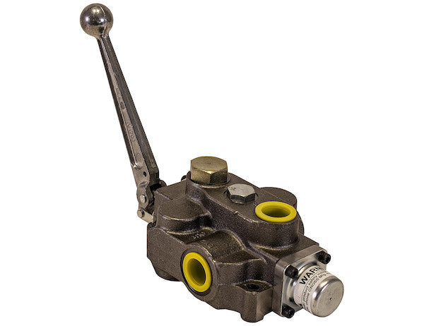
The 1 Spool Directional Control Valve from Buyers Products is compact, precise, and reliable. It directs flow smoothly where and when you need it. It's built of cast iron for durable, dependable performance. Small enough to fit anywhere, with plenty of force for the job, the control valve has a max flow of 30 GPM and a working pressure of 2500 PSI (maximum 4000 PSI). The integral relief valve is adjustable (factory-set at 2000 PSI/10 GPM). Each valve has a built-in load check to prevent flow reversal when shifting. Precision-machined and ground spools provide minimal leakage and smooth operation. The spool seals are external for easy replacement without having to disassemble the valve. The handle is sold separately. Additional configurations are available. Please contact Customer Service for further information.
Specifications
| Electrically Operated (y/n) | No |
|---|---|
| Inlet Port Size | 3/4 SAE ORB (-12) |
| Main Relief Setting | 2000 |
| Maximum Flow Rate | 30 |
| Maximum Pressure | 3500 |
| Out Port Size | #12 |
| Outlet Port Size | 3/4 SAE ORB (-12) |
| Port Type | SAE |
| Power Beyond (y/n) | No |
| Spool Action 1 | Power Up/Gravity Down |
| Spool Function | Single Acting 3 Way |
| Work Port Size | 3/4 SAE ORB (-12) |
Technical Deep Dive: 1 Spool Directional Control Valve with 3-Way Detent Out Configuration
The Buyers Products 1 Spool Directional Control Valve represents a pinnacle of hydraulic engineering, meticulously designed for applications demanding precise fluid power control in challenging environments. This comprehensive overview delves into the intricate technical specifications, operational principles, and robust construction that define this vital hydraulic component, ensuring users gain a thorough understanding of its capabilities and advantages.
Core Design and Functionality: Precision in Hydraulic Control
At its essence, a directional control valve is the brain of a hydraulic system, dictating the path of pressurized fluid to achieve desired mechanical motion. The 1 Spool Directional Control Valve is engineered for streamlined operation, focusing on reliability and efficiency in single-acting applications.
Single Spool Configuration
The designation "1 Spool" signifies that this valve is equipped with a solitary spool, making it ideally suited for controlling a single hydraulic actuator, such as a single-acting cylinder or a unidirectional hydraulic motor. This focused design optimizes the valve's footprint and internal complexity, yielding a compact unit that maintains robust performance. For systems requiring the independent control of multiple actuators, multi-spool valves would be necessary, but for dedicated single-function tasks, a 1-spool valve offers an efficient and cost-effective solution without unnecessary bulk or components.
3-Way Operation Explained
The "3-Way" aspect refers to the valve's porting configuration and its ability to connect three distinct fluid passages: the Pressure (P) port from the pump, the Tank (T) port for fluid return, and a single Work (A) port connected to the actuator. In its standard configuration for this valve, the spool's positions facilitate:
- Neutral (Hold) Position: In this central position, all ports (P, A, T) are typically blocked. This prevents fluid flow, holding the actuator in its current position under load. For a 3-way valve controlling a single-acting cylinder, this position isolates the cylinder, maintaining its extension or retraction as dictated by the external load.
- Power Up (Extend) Position: When the spool is shifted to this position, the Pressure (P) port is connected to the Work (A) port. This directs pressurized fluid to the actuator, causing it to extend or actuate. Concurrently, the Tank (T) port is blocked, ensuring maximum pressure delivery to the work port.
- Gravity Down (Retract) Position: Shifting the spool to this position connects the Work (A) port to the Tank (T) port, while the Pressure (P) port is blocked. This allows the hydraulic fluid to exhaust from the actuator, facilitating retraction under the influence of gravity or an external load. There is no pressurized fluid assisting the retraction; rather, it is a controlled release.
Detent Out Mechanism
A critical operational feature of this valve is the "Detent Out" mechanism. A detent is a mechanical locking device that holds the valve spool in a particular shifted position without requiring continuous manual pressure on the handle. In this context, "Detent Out" specifically refers to the spool being mechanically latched in the "Power Up" or "Extend" position. This feature is invaluable for operations that require an actuator to remain extended for an extended period, such as holding a dump bed in an elevated position or maintaining a plow's lift. The operator can engage the detent, release the control handle, and attend to other tasks, knowing the hydraulic function will remain engaged until manually released. This significantly enhances operator convenience, reduces fatigue, and improves overall system efficiency. To return the spool to the neutral position, a manual pull on the handle or, in some designs, a pressure kick-out feature (if integrated and specified for that detent) would disengage the detent.
Robust Construction and Material Science: Engineered for Durability
The longevity and consistent performance of any hydraulic component are inherently linked to its construction materials and manufacturing precision. This directional control valve exemplifies robust engineering through its choice of materials and meticulous fabrication processes.
Cast Iron Durability
The primary housing of the valve is constructed from high-grade cast iron. Cast iron is a preferred material for hydraulic valve bodies due to its exceptional properties:
- High Compressive Strength: It can withstand immense internal pressures and external stresses without deformation, ensuring structural integrity under demanding hydraulic loads.
- Vibration Dampening: Cast iron inherently possesses excellent vibration dampening characteristics, which helps to reduce noise, improve operational smoothness, and protect internal components from fatigue caused by hydraulic pulsations.
- Wear Resistance: Its microstructure provides inherent resistance to wear, critical for components with moving parts and fluid flow.
- Thermal Stability: Cast iron maintains its mechanical properties across a wide range of operating temperatures, crucial for reliable performance in varying environmental conditions.
- Corrosion Resistance: When properly treated and maintained, cast iron offers good resistance to common hydraulic fluids and environmental factors.
Precision Engineering: Spool and Bore
The operational integrity of a directional control valve hinges on the precision of its spool and the corresponding valve bore. This valve features "precision-machined and ground spools." This process ensures:
- Tight Tolerances: Machining and grinding create incredibly smooth surfaces and extremely tight clearances between the spool and the valve body. This minimizes internal leakage (also known as volumetric efficiency loss), ensuring that nearly all pressurized fluid is directed to the intended actuator, maximizing system power and reducing heat generation.
- Smooth Operation: The finely finished surfaces reduce friction, allowing the spool to shift smoothly and consistently, providing precise control and minimizing operator effort. This contributes to the valve's "minimal leakage and smooth operation" claim.
- Extended Lifespan: Reduced friction and wear on the spool and bore surfaces extend the operational life of the valve, even under frequent cycling.
Optimized Sealing: External Spool Seals
A significant design advantage incorporated into this valve is the use of "external spool seals for easy replacement." Unlike internal seals that often necessitate complete disassembly of the valve body for servicing, external seals are readily accessible. This feature offers substantial benefits:
- Reduced Downtime: Maintenance procedures for seal replacement are dramatically simplified and quicker to execute.
- Lower Maintenance Costs: Labor costs associated with servicing are reduced, and the need for specialized tools or extensive workshop time is minimized.
- Extended Valve Life: The ability to easily replace worn seals ensures that optimal sealing is maintained throughout the valve's operational life, preventing premature valve replacement due to minor leaks.
Advanced Hydraulic Performance: Flow, Pressure, and Safety
Beyond its construction, the valve’s hydraulic performance specifications are crucial indicators of its capacity and reliability within a system.
Flow and Pressure Dynamics
The valve is rated for a "max flow of 30 GPM" (Gallons Per Minute) and a "working pressure of 2500 PSI" (Pounds per Square Inch), with a "maximum pressure of 3500 PSI." These figures are critical for proper system design:
- Maximum Flow Rate (30 GPM): This rating indicates the maximum volume of hydraulic fluid the valve can efficiently pass without excessive pressure drop or internal heating. Matching this to the pump's output flow and the actuator's speed requirements is essential. A 30 GPM capacity makes this valve suitable for a wide range of medium-duty mobile and industrial applications.
- Working Pressure (2500 PSI): This is the recommended continuous operating pressure for the system. Operating within this range ensures optimal performance, component longevity, and safety.
- Maximum Pressure (3500 PSI): This represents the absolute peak pressure the valve can momentarily withstand without structural damage. While the product description mentions a "maximum 4000 PSI" for the valve's capability, the specification table clarifies the "Maximum Pressure" as 3500 PSI. It is paramount that system design respects this limit, using it as a safety margin against unexpected pressure spikes rather than a continuous operating parameter. This high maximum rating underscores the valve's robust construction and ability to handle transient pressure events.
Integrated Pressure Relief Valve
Safety and system integrity are paramount in hydraulic circuits. This valve incorporates an "integral relief valve," a critical component for protecting the entire system from overpressure conditions.
- Function: The relief valve acts as a pressure limiting device. If the system pressure exceeds the set value, the relief valve opens, diverting excess fluid directly back to the tank, thereby preventing damage to the pump, other system components, or the actuator.
- Adjustability: The relief valve is adjustable, allowing for fine-tuning to match the specific pressure requirements of different applications. This versatility ensures that the valve can be integrated into diverse systems with varying load capacities and actuator types.
- Factory-Set at 2000 PSI/10 GPM: The factory setting provides a ready-to-use configuration for many common applications. The "10 GPM" aspect relates to the flow rate at which the relief valve's pressure setting is calibrated. It specifies the flow through the relief valve when it begins to open and pass fluid at the stated pressure, ensuring accurate pressure limiting regardless of pump size (within reasonable limits).
Load Holding and Safety: Built-in Load Check
The valve features a "built-in load check to prevent flow reversal when shifting." A load check valve, also known as an anti-cavitation check valve or pilot-operated check valve, plays a crucial role in maintaining control and safety in hydraulic systems.
- Preventing Uncontrolled Movement: When a directional control valve is shifted (e.g., from neutral to power up), there can be a momentary dip in system pressure before full pressure is established at the work port. Without a load check, a heavy load on the actuator could momentarily reverse flow, causing an uncontrolled drop or drift. The load check immediately blocks reverse flow, ensuring that the load remains stable until the pump pressure fully takes over.
- Enhancing Safety: This feature significantly improves operational safety by preventing unexpected or rapid movements of the hydraulic actuator, protecting both operators and equipment.
- Smooth Operation: By maintaining a positive hold on the load, the load check contributes to smoother and more predictable actuator movements, enhancing precision and control during critical operations.
Porting and System Integration: Standardized Connectivity
Efficient integration into a hydraulic circuit relies on standardized and robust port connections.
SAE ORB (O-Ring Boss) Standard
All ports – Inlet, Outlet, and Work – are specified as "3/4 SAE ORB (-12)." SAE ORB fittings are the industry standard for high-pressure hydraulic applications, offering distinct advantages over traditional NPT (National Pipe Taper) threads:
- Superior Sealing: ORB fittings utilize an O-ring to create a positive, leak-proof seal between the fitting and the port face. This significantly reduces the risk of hydraulic fluid leakage, a common issue with NPT connections, especially under high pressure and vibration.
- Reusable: Unlike NPT threads which can be prone to wear and deformation, ORB fittings can be disassembled and reassembled multiple times without compromising the seal, simplifying maintenance.
- Reduced Assembly Torque: Less torque is required to achieve a secure seal compared to NPT, minimizing the risk of overtightening and damaging components.
- Elimination of Sealants: The O-ring inherently provides the seal, largely eliminating the need for thread sealants, which can sometimes contaminate hydraulic fluid.
Connectivity Overview
- Inlet Port Size: 3/4 SAE ORB (-12): Connects directly from the hydraulic pump, receiving the pressurized fluid.
- Outlet Port Size: 3/4 SAE ORB (-12): Returns exhausted fluid from the valve back to the hydraulic reservoir (tank).
- Work Port Size: 3/4 SAE ORB (-12): The single port that connects to the hydraulic actuator (e.g., a single-acting cylinder's base end).
Operational Characteristics: Manual Actuation and Spool Action
The operational nature of this valve is defined by its manual control and specific spool action, making it suitable for direct operator engagement.
Manual Actuation
As explicitly stated, the valve is "Electrically Operated (y/n): No." This confirms that it is a manually operated valve, requiring direct physical manipulation of a handle (sold separately) to shift the spool. Manual operation is often preferred in applications where:
- Direct Operator Control is Essential: For tasks requiring immediate and tactile feedback from the hydraulic system.
- Simplicity and Robustness: Manual valves typically have fewer electronic components, making them simpler to troubleshoot and more resilient in harsh operating environments without concerns about electrical failures.
- Cost-Effectiveness: They generally represent a more economical solution compared to solenoid-operated or pilot-operated valves.
Spool Action: Power Up/Gravity Down
The "Spool Action 1: Power Up/Gravity Down" reiterates the specific functionality tailored for single-acting cylinders. In this configuration, hydraulic pressure is utilized only for the "up" or "extend" stroke of the actuator. The "down" or "retract" stroke relies on an external force, typically gravity acting on the load or the weight of the implement itself. This design is highly efficient for applications where the load naturally assists in the return stroke, conserving hydraulic power by not requiring pressure for retraction. The detent mechanism further enhances this by holding the "power up" position, allowing for sustained lifting without continuous operator engagement.
Applications and Versatility
The compact size and robust performance characteristics of this 1 Spool Directional Control Valve make it exceptionally versatile across a spectrum of mobile and industrial hydraulic applications. Its design is particularly well-suited for:
- Dump Trailer and Dump Truck Applications: Ideal for controlling the lifting and lowering of dump beds, leveraging the "Power Up/Gravity Down" action for efficient operation.
- Snow Plows and Other Front-Mounted Implements: Used for lifting and lowering snow plows, utility blades, or other implements where gravity assists in the return.
- Agricultural Machinery: Suitable for controlling single-acting functions on tractors or farm implements, such as lifting cultivators or plows.
- Material Handling Equipment: For single-acting lift functions on small forklifts, scissor lifts, or platform lifts.
- Utility Vehicles and Service Trucks: Controlling auxiliary hydraulic functions that require simple, robust, single-acting control.
Maintenance and Longevity
The design of the Buyers Products 1 Spool Directional Control Valve is inherently geared towards maximizing service life and minimizing maintenance burden. The cast iron construction provides the foundational durability, resisting wear and fatigue over countless operational cycles. The precision-machined spools and bores, while contributing to efficiency, also play a role in longevity by reducing internal friction and wear. Crucially, the external spool seals stand out as a key feature for simplified maintenance. This design choice ensures that typical wear components, such as seals, can be replaced quickly and efficiently, significantly extending the valve's operational life without requiring a complete unit overhaul. The adjustable integral relief valve further contributes to longevity by safeguarding the system against potentially damaging overpressure events, thus protecting not only the valve itself but also other expensive hydraulic components within the circuit. Adherence to recommended hydraulic fluid cleanliness standards and regular inspection of hydraulic connections will further ensure optimal performance and extend the lifespan of this durable valve.
Conclusion
The 1 Spool Directional Control Valve with a 3-Way Detent Out configuration from Buyers Products is a testament to robust engineering and functional precision. Its cast iron construction, precision-machined components, and thoughtful features like external spool seals, an integral adjustable relief valve, and a built-in load check combine to deliver a hydraulic control solution that is durable, reliable, and highly efficient. Designed for manual operation in single-acting, Power Up/Gravity Down applications, it provides the compact power and precise control essential for a broad spectrum of mobile and industrial equipment. With its 30 GPM flow capacity and 2500 PSI working pressure, it stands as an exemplary choice for engineers and operators seeking dependable performance and ease of maintenance in demanding hydraulic systems. For specific application requirements or alternative configurations, Customers are encouraged to contact Customer Service to explore tailored solutions.