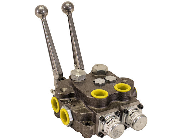
The 2 Spool Directional Control Valve from Buyers Products is compact, precise, and reliable. It directs flow smoothly where and when you need it. It's built of cast iron for durable, dependable performance. Small enough to fit anywhere, while allowing plenty of force for the job, the control valve is rated at 30 GPM and a working pressure of 2500 PSI (maximum 4000 PSI ). The integral relief valve is adjustable (factory-set at 2000 PSI /10 GPM). Each valve has a built-in load check to prevent flow reversal when shifting. Precision-machined and ground spools provide minimal leakage and smooth operation. The spool seals are external for easy replacement without having to disassemble the valve. Choose from a variety of 3-way or 4-way spool actions. They are available with or without Power Beyond, or with an option to convert to Power Beyond. The handle is sold separately. Additional configurations are available. Please contact Customer Service for further information.
Specifications
| Electrically Operated (y/n) | No |
|---|---|
| Inlet Port Size | 3/4 SAE ORB (-12) |
| Main Relief Setting | 2000 |
| Maximum Flow Rate | 30 |
| Maximum Pressure | 3500 |
| Outlet Port Size | 3/4 SAE ORB (-12) |
| Power Beyond (y/n) | No |
| Spool Action 1 | Power Up/Power Down |
| Spool Action 3 | Power Up/Power Down |
| Work Port Size | 3/4 SAE ORB (-12) |
Advanced Technical Overview: The Buyers Products 2-Spool Directional Control Valve
The Buyers Products 2-Spool Directional Control Valve, featuring a consistent 4-way spring-center configuration for both spools, represents a cornerstone in modern hydraulic system design. Engineered for robust performance and exceptional reliability, this valve is meticulously crafted to manage complex hydraulic circuits with precision and efficiency. Its design is predicated on the fundamental requirements of mobile and industrial hydraulic applications, where the accurate direction and control of fluid power are paramount to operational success and safety.
Core Functional Principles: Two Spools, Four-Way, Spring-Centering Mechanism
At the heart of this component's utility are its two independently operable spools. Each spool functions as a discrete control element, enabling the simultaneous or sequential management of two separate hydraulic actuators or circuits. This dual-spool architecture significantly enhances system versatility, allowing for the concurrent operation of distinct hydraulic functions, such as lifting and tilting, or extending and retracting, from a single, integrated valve block. This reduces system complexity and installation footprint compared to using two separate single-spool valves.
The designation "4-way" refers to the four principal ports associated with each spool: a pressure inlet (P), a tank return (T), and two work ports (A and B). This configuration permits four distinct flow paths relative to the neutral position: directing pressurized fluid from P to A while returning B to T (e.g., extend); directing P to B while returning A to T (e.g., retract); a neutral position where all ports may be blocked or certain ports are open to tank; and a float position in some variants (though not explicitly stated for this spring-centered model, which typically means a closed-center neutral). For this valve, the "Power Up/Power Down" spool action confirms its utility in driving double-acting cylinders, where hydraulic pressure is applied to both sides of the piston for controlled extension and retraction.
The "spring-center" mechanism is a crucial safety and operational feature. Upon release of the control lever, internal springs automatically return the spool to its neutral position. In this neutral state, the work ports (A and B) are typically blocked, effectively locking the hydraulic actuator in its last position and preventing unintended movement. This ensures static load holding and provides a failsafe condition, preventing uncontrolled motion of connected equipment in the absence of operator input. This characteristic is particularly vital in applications involving lifting, tilting, or positioning heavy loads, where maintaining a stable position is critical for safety and precision.
Robust Construction and Material Science: Cast Iron Durability
The choice of cast iron for the valve body is a testament to its engineering for durability and sustained performance in demanding environments. Cast iron offers several intrinsic advantages for hydraulic components:
- High Tensile Strength and Rigidity: Cast iron possesses excellent compressive strength and rigidity, providing a robust housing capable of withstanding the significant internal pressures and external forces encountered in hydraulic systems, particularly those operating up to 3500 PSI maximum.
- Vibration Damping: The inherent microstructure of cast iron provides superior vibration damping characteristics compared to other metals. This helps to absorb hydraulic shock and reduce noise levels, contributing to smoother system operation and extended component life by minimizing stress on internal parts.
- Thermal Stability: Cast iron maintains its structural integrity and dimensional stability across a wide range of operating temperatures, which is essential for consistent valve performance in varying climatic conditions or under continuous heavy-duty cycles where hydraulic fluid temperatures can fluctuate.
- Wear Resistance: The material exhibits good wear resistance, especially in critical areas where spools interface with the valve bore, contributing to the long-term maintenance of sealing integrity and minimal internal leakage.
- Cost-Effectiveness: While technically advanced, cast iron remains a cost-effective material for high-volume manufacturing of hydraulic components, enabling the production of reliable valves at a competitive price point.
Performance Specifications: Flow, Pressure, and System Protection
The valve's operational parameters are carefully specified to meet the demands of a broad range of hydraulic systems:
- Maximum Flow Rate (30 GPM): A flow rate of 30 Gallons Per Minute (GPM) indicates the valve's capacity to handle a substantial volume of hydraulic fluid. This flow rate is suitable for applications requiring moderate to high speeds for actuator movement. For instance, in a system operating a hydraulic cylinder, a 30 GPM flow rate directly correlates to how quickly the cylinder can extend or retract. Adequate flow capacity prevents bottlenecks in the hydraulic circuit, ensuring responsive and efficient system operation for tasks such as lifting large loads quickly, rapid implement articulation, or efficient material transfer.
- Working Pressure (2500 PSI) and Maximum Pressure (3500 PSI): The specified working pressure of 2500 PSI represents the optimal continuous operating pressure for which the valve is designed, ensuring longevity and consistent performance. The maximum pressure rating of 3500 PSI signifies the peak transient pressure the valve can safely withstand without structural failure or permanent deformation. It is crucial for system designers to ensure that the operating pressure of their hydraulic system does not consistently exceed the working pressure and never surpasses the maximum pressure rating, thereby safeguarding the integrity of the valve and the entire hydraulic circuit. The disparity between the description's 4000 PSI and the specifications table's 3500 PSI for maximum pressure should be noted, with the table's 3500 PSI being the definitive maximum rating for critical safety and design considerations.
- Integral Relief Valve (Adjustable, factory-set at 2000 PSI / 10 GPM): An integral relief valve is a critical safety and system protection component. It prevents over-pressurization of the hydraulic system by diverting excess fluid back to the tank once a preset pressure threshold is reached. This protects pumps, actuators, hoses, and other components from damage due to excessive pressure spikes. The valve is adjustable, allowing system designers to fine-tune the maximum system pressure to match the requirements of specific applications or to protect sensitive components downstream. The factory setting of 2000 PSI provides a robust starting point for many applications, with the 10 GPM flow rate likely indicating the flow capacity at which this pressure relief is effectively managed, or the bypass capacity under relief conditions. Adjustability ensures adaptability across diverse hydraulic system requirements and load profiles.
Advanced Hydraulic Functionality: Load Checks and Spool Design
Beyond the fundamental flow and pressure control, the valve incorporates advanced features designed to enhance performance and reliability:
- Built-in Load Check: Each valve incorporates a built-in load check, a non-return valve strategically placed within the flow path. The primary function of a load check is to prevent flow reversal when the spool is shifted from its neutral position, particularly under a suspended load. Without a load check, a sudden drop in pressure during the initial stages of spool movement could cause an actuator to momentarily "drift" or "fall" before the main pressure path is fully established. The load check ensures that the actuator remains firmly held, preventing uncontrolled movement and providing smooth, immediate engagement of the load once the spool is activated. This is invaluable for maintaining control and safety, especially with heavy or unstable loads.
-
Precision-Machined and Ground Spools: The quality of the spools is paramount to valve performance. The spools in this valve are precision-machined and ground, processes that result in exceptionally tight tolerances and ultra-smooth surface finishes. This meticulous manufacturing yields several benefits:
- Minimal Leakage: The precise fit between the spool and the valve bore significantly reduces internal (bypass) leakage. Minimizing leakage improves volumetric efficiency, ensuring that more of the pump's output is converted into useful work and reducing heat generation within the system.
- Smooth Operation: The highly polished surfaces and accurate dimensions of the spools reduce friction during shifting, enabling smooth, low-effort operation. This contributes to better operator control and reduces wear on the spool and bore, extending the valve's service life.
- Consistent Performance: Precision manufacturing ensures consistent flow characteristics and pressure drop across the valve, leading to predictable and repeatable system performance.
- External Spool Seals for Easy Replacement: Maintenance efficiency is a key consideration in industrial and mobile equipment. The design featuring external spool seals allows for their replacement without the need to disassemble the entire valve body. This significantly reduces maintenance time and complexity, minimizing downtime and associated costs. Easy access to seals extends the operational life of the valve by enabling proactive and reactive seal maintenance, preventing minor leaks from escalating into major system issues.
Connectivity and Configuration Options: Port Sizes and Power Beyond
System integration and flexibility are addressed through standardized porting and optional features:
- Inlet, Outlet, and Work Port Sizes (3/4 SAE ORB -12): The consistent use of 3/4 SAE ORB (-12) fittings across all inlet, outlet, and work ports simplifies system design and hose routing. SAE ORB (Society of Automotive Engineers O-Ring Boss) fittings are highly regarded for their superior leak-free performance compared to traditional tapered thread fittings. The O-ring provides a robust seal that is less susceptible to vibration-induced loosening or pressure surges. The -12 designation corresponds to a specific thread size and diameter (typically for 3/4 inch nominal tubing), ensuring compatibility with standard hydraulic hoses and fittings readily available in the market. This standardization eases installation and component procurement.
- Power Beyond Capability: The option for "Power Beyond" functionality is a significant advantage for complex hydraulic systems requiring multiple directional control valves in series. A Power Beyond port allows pressurized fluid to be routed from the outlet of the initial valve to the inlet of a subsequent valve, even when the first valve's spools are in the neutral position. This means that a single hydraulic pump can supply multiple functions, with the unused flow from one valve being available for the next valve in the circuit, all while maintaining system pressure. The availability "with or without Power Beyond, or with an option to convert to Power Beyond" provides unparalleled flexibility, allowing users to configure the valve precisely for their specific system architecture, whether it's a standalone circuit or part of a larger, integrated hydraulic network.
Operational Interface and Versatility: Manual Control and Customization
This valve is designed for direct manual operation, eschewing electrical actuation for simplicity and robustness in environments where electrical components might be susceptible to damage or where a direct mechanical interface is preferred. The "Electrically Operated (y/n): No" specification highlights this characteristic, making it ideal for straightforward, operator-driven applications. The handle, sold separately, allows for customization based on operator preference and mounting orientation, ensuring ergonomic and efficient control.
The flexibility extends to "a variety of 3-way or 4-way spool actions," though the title specifies 4-way for both spools in this particular model. This indicates the broader product family's versatility, but for the specified product, the consistent 4-way spring center with "Power Up/Power Down" action for both spools (as indicated by Spool Action 1 and Spool Action 3) confirms its primary application in controlling double-acting cylinders for lifting, lowering, extending, and retracting operations. The mention of "Additional configurations are available" further underscores Buyers Products' commitment to meeting diverse customer needs, encouraging direct consultation with Customer Service for highly specialized requirements.
Typical Applications and Industry Relevance
Given its robust design, technical specifications, and dual-spool configuration, this directional control valve is ideally suited for a wide array of mobile and industrial hydraulic applications, including but not limited to:
- Mobile Equipment: Dump trucks and trailers, snowplows, salt and sand spreaders, refuse vehicles (e.g., packer blade control), agricultural machinery (e.g., tractor implements like loaders, plows, and cultivators), forestry equipment, and utility service vehicles.
- Material Handling: Small to medium-sized forklifts, lifting platforms, scissor lifts, and various types of conveyor systems requiring hydraulic actuation.
- Construction Machinery: Skid-steer loaders, compact excavators, backhoes, and other light-to-medium construction equipment where precise control of attachments is essential.
- Industrial Hydraulics: Machine tools, presses, and other stationary industrial equipment requiring dual-axis hydraulic control, particularly in environments where manual, robust control is preferred over electronic.
Installation, Maintenance, and System Integration Best Practices
Proper installation and integration are paramount to leveraging the full potential of this directional control valve. Users should adhere to industry best practices:
- Mounting: The valve should be securely mounted to a rigid surface, ensuring stability and minimizing vibration. Consideration for handle clearance and operator ergonomics is important.
- Fluid Compatibility: Use hydraulic fluids that meet the manufacturer's specifications and are compatible with the valve's internal seals and materials. Proper fluid selection is crucial for optimal performance and longevity.
- Filtration: Implementing a robust filtration system upstream of the valve is essential. Contaminants are a leading cause of premature wear in hydraulic components, particularly precision-machined spools and bores. Fine filtration will extend the life of the valve and other system components.
- Pressure Settings: The integral relief valve should be adjusted to the appropriate pressure setting for the specific application, considering the maximum allowable pressure for all components in the hydraulic circuit. This adjustment should only be performed by qualified personnel.
- Hose and Fitting Selection: All hoses, tubing, and fittings connected to the 3/4 SAE ORB (-12) ports must be rated for the system's maximum operating pressure and flow rate to ensure safety and prevent leaks.
- Regular Inspection: Periodically inspect the valve for external leaks, especially at the external spool seals, and address them promptly. Check for any signs of physical damage or excessive wear.
Conclusion
The Buyers Products 2-Spool Directional Control Valve with its dual 4-way spring-center configuration is an expertly engineered solution for demanding hydraulic applications. Its combination of rugged cast iron construction, high flow and pressure capabilities, critical safety features like the integral relief valve and load checks, and design for easy maintenance (external spool seals) positions it as a superior choice for controlling complex hydraulic functions. Whether utilized in mobile equipment, agricultural machinery, or industrial systems, this valve delivers the precision, reliability, and durability required to ensure efficient and safe hydraulic operation, making it an indispensable component for professionals seeking uncompromising performance.