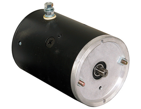
Operate your pump, plow, or lift gate with the Clockwise Rotation Motor with Spline Output Shaft from Buyers Products. Featuring a 12V DC motor and a nine-spline output shaft, this unit offers a maximum 200A output.
Specifications
| Case Grounded (y/n) | Yes |
|---|---|
| Diameter | 4.5 |
| Gear Ratio | - |
| Max Current | 200 |
| Mounting Pattern | 2 Stud |
| Power | 1.6 |
| Rotation | Clockwise |
| Shaft Diameter | 0.500 |
| Shaft Type | Splined |
| Speed | 2550 |
| Voltage | 12 |
| Warranty | - |
| Wattage | 2400 |
Advanced Technical Overview: Clockwise Rotation Motor with Spline Output Shaft
The Clockwise Rotation Motor with Spline Output Shaft from Buyers Products represents a robust and precisely engineered solution for demanding mobile and industrial hydraulic applications. Designed for optimal performance in systems requiring reliable rotary power, this unit is particularly suited for operating essential components such as hydraulic pumps in lift gates, snow plows, and various other lifting or motive applications. Its technical specifications and design features are meticulously chosen to ensure high efficiency, durability, and seamless integration into a wide array of existing and new systems.
Core Operational Parameters and Electrical Characteristics
At the heart of this motor's functionality is its 12V DC operating voltage. The selection of a 12V DC system is foundational for numerous mobile applications, providing direct compatibility with standard automotive and heavy-duty vehicle electrical architectures. This voltage level is critical for minimizing energy losses over typical wiring distances in vehicle-mounted equipment, while also being sufficiently powerful to drive significant loads. The direct current (DC) operation simplifies power supply requirements, relying on readily available battery banks.
The motor is capable of delivering a maximum current of 200 Amperes. This high current capacity is a direct indicator of the motor's substantial power output capability, particularly under peak load conditions. A motor designed to handle 200A implies robust internal windings, heavy-duty brushes (if a brushed motor), and robust commutator design, all engineered to withstand the thermal and mechanical stresses associated with high current flow. Proper system design, including appropriate wire gauge selection and overcurrent protection (fuses or circuit breakers), is paramount to safely leverage this capability and protect both the motor and the electrical system from potential damage due to sustained high loads or short circuits.
With a specified power output of 1.6 horsepower (HP), which translates directly to 2400 Watts (W), this motor delivers considerable mechanical energy for its compact 4.5-inch diameter footprint. The relationship between power (P), voltage (V), and current (I) in a DC circuit (P = V * I) underscores the efficiency of this unit. At 12V, a 200A draw theoretically yields 2400W (2.4 kW) of electrical input power. The 1.6 HP output (approximately 1193.16 Watts) indicates that the motor is designed for sustained, high-torque applications. The difference between input electrical power and output mechanical power is accounted for by the motor's efficiency, which converts electrical energy into mechanical work while dissipating some energy as heat. This 1.6 HP is ample for initiating movement against significant resistive forces, such as lifting heavy loads or operating hydraulic pumps under pressure.
The motor operates at a nominal speed of 2550 RPM (revolutions per minute). This rotational speed is a critical parameter, particularly when coupling the motor to hydraulic pumps or other driven components. For hydraulic pumps, the input RPM directly influences the pump's flow rate, and consequently, the speed of actuator movement (e.g., lift gate ascent/descent). For winches, motor RPM, in conjunction with gearbox ratios, determines the line speed. The 2550 RPM is a relatively high speed, suggesting that for applications requiring lower speeds but higher torque, a reduction gearbox would typically be employed. This allows for optimization of output torque and speed to match the specific demands of the application, maximizing the motor's operational envelope.
Mechanical Design and Torque Transmission
A defining characteristic of this unit is its Clockwise Rotation. The direction of rotation is a non-negotiable specification for many mechanical and hydraulic systems. For instance, hydraulic gear pumps are often uni-directional, meaning they are designed to pump fluid effectively only when their input shaft rotates in a specific direction. Installing a motor with an incorrect rotation can lead to inefficient operation, damage to the pump, or complete system failure. The explicit designation of "Clockwise Rotation" (CW) ensures compatibility with the vast majority of standard hydraulic pump designs that require a CW input when viewed from the shaft end. This precise specification eliminates ambiguity and facilitates correct system integration.
The motor features a Splined Output Shaft with nine splines and a diameter of 0.500 inches. The use of a splined shaft represents a significant engineering advantage over alternative coupling methods, such as keyways or set screws, particularly in applications involving high torque transfer and frequent reversals. Splines are integral teeth on the shaft that mate with corresponding grooves in a hub or coupling, distributing the torque load over a much larger surface area compared to a single key. This distribution minimizes stress concentrations, drastically reducing the likelihood of shearing, wear, and play over time. The nine-spline configuration, combined with the 0.500-inch diameter, provides a robust and positive engagement, ensuring efficient and reliable transmission of the motor's full torque output to the driven component. This design choice contributes significantly to the overall durability and longevity of the power train, especially in dynamic and shock-loaded environments common to hydraulic and lifting applications.
The 4.5-inch diameter of the motor case suggests a balance between compactness and structural integrity. The housing is designed to encapsulate and protect the internal components, including the armature, field windings, brushes, and bearings, from environmental ingress and mechanical impact. While specific material is not listed, typically, such motors utilize heavy-duty steel or cast aluminum alloy housings known for their strength-to-weight ratio and heat dissipation properties. A robust housing is crucial for applications subjected to vibration, moisture, and temperature fluctuations, ensuring consistent performance and extended operational life.
The motor employs a 2 Stud Mounting Pattern. This standard mounting configuration provides a secure and stable interface for attaching the motor to its mounting surface or directly to the driven equipment. The two-stud pattern is widely adopted in the industry, simplifying installation and replacement. The exact stud dimensions and spacing would be critical for specific application matching, but the general pattern indicates a straightforward and reliable mechanical attachment strategy. Proper mounting is essential not only for structural integrity but also to manage vibrations and ensure precise alignment with the driven component, thereby preventing premature wear on bearings and couplings.
The specification of Case Grounded (Yes) is an important electrical and safety feature. A case-grounded motor means that one side of the motor's electrical circuit (typically the negative terminal) is electrically connected to the motor's external metallic housing. This simplifies wiring in many mobile applications, as the vehicle chassis can serve as the common ground path, reducing the number of wires required. More importantly, it provides a safety mechanism; in the event of an internal electrical fault where a live wire contacts the motor casing, the current will flow directly to the vehicle's chassis ground, typically triggering a fuse or circuit breaker and preventing the casing from becoming energized, thus protecting operators from electrical shock. This design is standard for many automotive and heavy equipment applications due to its practical advantages in wiring and inherent safety features.
Applications and Operational Context
The design and specifications of this Clockwise Rotation Motor with Spline Output Shaft make it an ideal choice for a variety of demanding applications. Its primary suitability for pumps, plows, and lift gates highlights its versatility in hydraulic systems:
- Hydraulic Power Units (HPUs): This motor is a perfect prime mover for compact hydraulic power units that require 12V DC input. These units are commonly found in utility vehicles, dump trailers, snow plows, and vehicle-mounted cranes. The clockwise rotation directly drives standard uni-directional gear pumps, producing hydraulic pressure and flow for actuating cylinders and motors. The 1.6 HP power ensures adequate pressure and flow for typical auxiliary functions.
- Lift Gate Mechanisms: For truck and trailer lift gates, reliable and powerful DC motors are essential. This motor provides the necessary force to operate the hydraulic pump that powers the lifting and lowering cylinders, ensuring efficient and safe cargo handling. The robust spline shaft is critical for handling the transient and impact loads associated with lifting and lowering operations.
- Snow Plow Hydraulics: Snow plows require quick and powerful hydraulic response for raising, lowering, and angling the blade. This motor's 12V DC power, high current capacity, and specific rotation make it an excellent choice for powering the hydraulic pump in these systems, enabling responsive control even in harsh winter conditions.
- Winches and Hoists: While primarily geared towards hydraulic pumps, the motor's high torque and robust shaft could also be adapted for certain winch or hoist applications, especially those requiring precise clockwise winding. Integration with an appropriate gearbox would be necessary to achieve desired pulling speeds and torque multiplication.
- Industrial and Agricultural Auxiliary Equipment: Beyond the specified applications, this motor is suitable for a wide range of auxiliary functions in industrial and agricultural machinery, such as operating small conveyors, actuators, or specialized tools that benefit from a compact, powerful, and reliable DC power source.
Integration and Installation Considerations
Successful integration of this motor into an application requires careful attention to several engineering principles:
- Electrical System Design: Given the 200A maximum current draw, proper cable sizing is critical to prevent voltage drop and excessive heat generation in the wiring. Cables should be rated for the maximum continuous current plus a safety margin, with consideration for cable length. Overcurrent protection (fuses or circuit breakers) must be sized appropriately, typically 125% of the expected continuous load, to protect the motor and wiring from overloads. Battery capacity in the host vehicle or system must be sufficient to supply the peak current demands without excessive voltage sag, which can degrade motor performance and battery life.
- Mechanical Alignment: Precise alignment between the motor's splined output shaft and the driven component's input shaft is paramount. Misalignment can lead to premature wear of bearings, couplings, and the splines themselves, causing vibration, noise, and ultimately, system failure. Specialized coupling components designed for splined shafts, such as flexible couplings, can help mitigate minor misalignments and absorb shock loads.
- Thermal Management: While not explicitly detailed, all electric motors generate heat during operation, especially under heavy loads. The 2400W electrical input with 1.6 HP output implies a certain level of power dissipation as heat. The 4.5-inch diameter casing likely offers some passive cooling surface, but for applications requiring continuous or extended heavy-duty cycles, monitoring motor temperature and ensuring adequate airflow around the motor is advisable to prevent overheating and extend motor life. Duty cycle limitations might apply depending on the specific application and ambient conditions.
- Environmental Protection: While the robust housing implies a certain level of durability, for applications in extremely harsh environments (e.g., direct exposure to corrosive chemicals, saltwater spray, very fine dust), additional protective measures or enclosures might be considered to safeguard the motor's internal components.
- Maintenance: Like all electromechanical devices, periodic inspection and maintenance are recommended. This typically includes checking electrical connections for tightness and corrosion, inspecting motor brushes (if applicable) for wear, and ensuring mounting hardware remains secure. The "Case Grounded" design simplifies electrical diagnostics in some cases.
Conclusion
The Clockwise Rotation Motor with Spline Output Shaft by Buyers Products is a high-performance, purpose-built electric motor designed for critical auxiliary functions in mobile and industrial settings. Its carefully selected specifications—12V DC operation, 1.6 HP (2400W) power, 200A maximum current, 2550 RPM speed, clockwise rotation, and a durable nine-spline output shaft—collectively ensure robust and reliable power delivery. The case-grounded design and 2-stud mounting pattern further enhance its ease of integration and safety. For engineers and technicians seeking a dependable and powerful rotary solution for hydraulic pumps in lift gates, snow plows, and similar heavy-duty applications, this motor offers a technically sound and operationally proven component capable of withstanding the rigors of demanding environments. Its precise engineering for torque transfer and specific rotational requirements minimizes compatibility issues and maximizes operational longevity, making it a highly valuable asset for a wide range of industrial and mobile equipment.